Squeezing dewatering equipment

A technology of extrusion dehydration and equipment, applied in water/sludge/sewage treatment, chemical instruments and methods, sludge treatment, etc., can solve the problems of not considering the equal-diameter structure, unable to realize manual connection, and single function, etc., to achieve Improve space utilization and avoid effects that cannot be driven by manpower

Pending Publication Date: 2021-03-16
CHANGSHA UNIVERSITY OF SCIENCE AND TECHNOLOGY
View PDF15 Cites 2 Cited by
  • Summary
  • Abstract
  • Description
  • Claims
  • Application Information

AI Technical Summary

Problems solved by technology

[0005] 1. The dredging equipment in the prior art separates sewage through the filter screen, but the silt falling from a high place will impact the filter screen, and the impact force will cause undesired substances to pass through the filter screen, or the impact force will damage the filter screen
[0006] 2. In the prior art dredging equipment, the screw extrusion column is often of equal-diameter structure, but the equal-diameter structure does not consider many factors such as: the size of the passage space of the medium and the extrusion force of the medium, so the function is single
[0007] 3. In the dredging equipment of the prior art, the screw extrusion column is driven by a motor, but the motor often needs to be additionally equipped with a riser or a support frame, which increases the volume and increases the cost
[0008] 4. The dredging equipment in the prior art is often discharged directly after the sludge is squeezed, and lacks the on-off control and adjustment of the sludge discharge. In some special working conditions such as when the downstream storage room is full, it cannot be switched on and off in time. Manual intervention, watching downstream storage chambers to prevent overfilling
[0009] 5. The dredging equipment in the prior art has cleaning needs, and an additional independent cleaning channel will be provided. However, if additional functions such as valve functions and manual drive functions are added, the superposition of too many functions will lead to increased costs and increased volume. Big
[0010] 6. In the dredging equipment of the prior art, the screw extrusion column is driven by a motor, which cannot be manually taken over in an emergency. There may be a technology that is driven by a motor or a manual drive device at the same time, but this drive does not consider the manual drive device Rotation arm size

Method used


Image

  • Squeezing dewatering equipment
  • Squeezing dewatering equipment
  • Squeezing dewatering equipment

Examples


Embodiment Construction

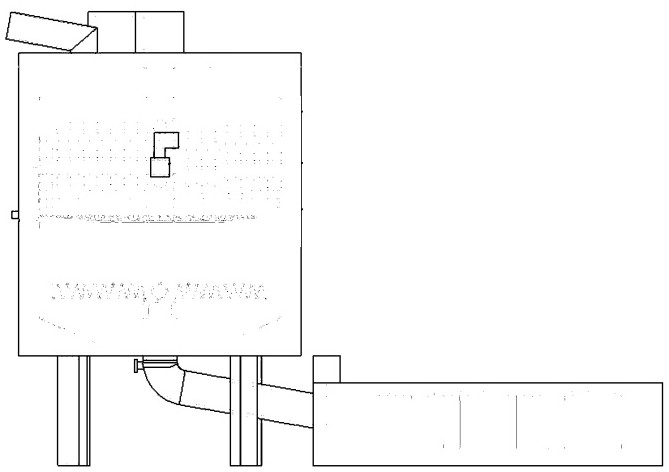
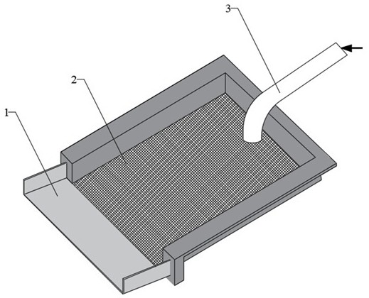
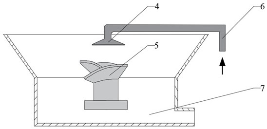
[0042] As shown in the figure: a extrusion dehydration equipment, including the main body, mud outlet regulating valve, upper plate, filter screen, sludge dewatering chamber, screw extrusion column, separated water collection tank, water collecting plate, separated water outlet, Demineralized block outlet, closing plate, manual drive device, first guide plate, second guide plate, sewage outlet, impact plate, right side wall, left side wall, inner cylinder, motor, outer cylinder; The port regulating valve includes a driving part, a valve stem and a valve core.

[0043] Wherein the upper part of the main body is provided with an upper plate, the right side of the upper plate is provided with a sludge inlet, the middle part of the main body is provided with a filter screen, and the sludge dehydration chamber is provided between the filter screen and the upper plate, and the sludge The dewatering chamber is provided with the spiral extruding column, and the right side of the filte...


PUM


Abstract

Squeezing dewatering equipment comprises a main body, a sludge outlet adjusting valve, an upper plate, a filter screen, a sludge dewatering cavity, a spiral squeezing column, a separated water collecting tank, a water collecting plate, a separated water discharge port and a dewatered sludge block outlet, wherein an upper plate is arranged above the main body, a sludge inlet is formed in the rightside of the upper plate, a filter screen is arranged in the middle of the main body, the sludge dewatering cavity is formed between the filter screen and the upper plate, the spiral squeezing column is arranged in the sludge dewatering cavity, and an impact-resistant plate is arranged at the position, corresponding to the sludge inlet, of the right side of the filter screen.

Description

technical field [0001] The invention relates to the field of urban pipeline dredging, in particular to a squeeze dehydration device. Background technique [0002] Silt is a common sediment in urban pipelines, mainly distributed in urban road sewers, reservoirs, sewage pipes, etc., containing a large amount of impurities such as clay, sand, and organic sediments. Silt is easy to adhere to the inner wall of the pipeline, forming a silt layer, which hinders the sewer pipeline The water body flows, and the organic substances contained in it may ferment and deteriorate under the action of the environment, breed bacteria, and pollute the environment. With the development of cities in our country, the dredging of underground waterways is becoming more and more important. The rapid and efficient treatment of the silt cleaned from the pipeline is of great significance to the construction of the urban environment. The method of directly sucking out the sludge with a pump suction truc...

Claims


Application Information

Patent Timeline
Patent Type & Authority Applications(China)
IPC IPC(8): C02F11/125
CPCC02F11/125
Inventor 孙鹏程隆鹏王佳丽刘超毛聪尹来容
Owner CHANGSHA UNIVERSITY OF SCIENCE AND TECHNOLOGY
Why Eureka
Try Eureka