
Rotary oiling device and compressor

A technology for compressors and oil pipes, which is applied to components of pumping devices for elastic fluids, rotary piston type/swing piston type pump components, mechanical equipment, etc. Compressor cost and other issues, to achieve the effect of improving generalization rate, reducing manufacturing cost, and reducing parts

Active Publication Date: 2021-03-16
ZHUHAI GREE REFRIGERATION TECH CENT OF ENERGY SAVING & ENVIRONMENTAL PROTECTION
View PDF3 Cites 0 Cited by
  • Summary
  • Abstract
  • Description
  • Claims
  • Application Information

AI Technical Summary

Problems solved by technology

[0004] 1. There are many parts in the oil supply system, and there are many assembly processes, which increase the cost of the compressor
[0005] 2. Because the fan is installed on the rotor, the rotors of vertical and horizontal compressors are not universal, which affects the generalization
[0006] 3. The oil baffle plate, fan and other parts of the oil supply system need new mold opening, which takes a long time to open the mold, and requires new tooling and inspection tools, which affects the development and mass production cycle of the compressor

Method used


Image

  • Rotary oiling device and compressor
  • Rotary oiling device and compressor
  • Rotary oiling device and compressor

Examples


Embodiment Construction

[0033] In order for those skilled in the art to better understand the technical solution of the present invention, the present invention will be further described below in conjunction with the examples and accompanying drawings, but the embodiments of the present invention are not limited thereto.

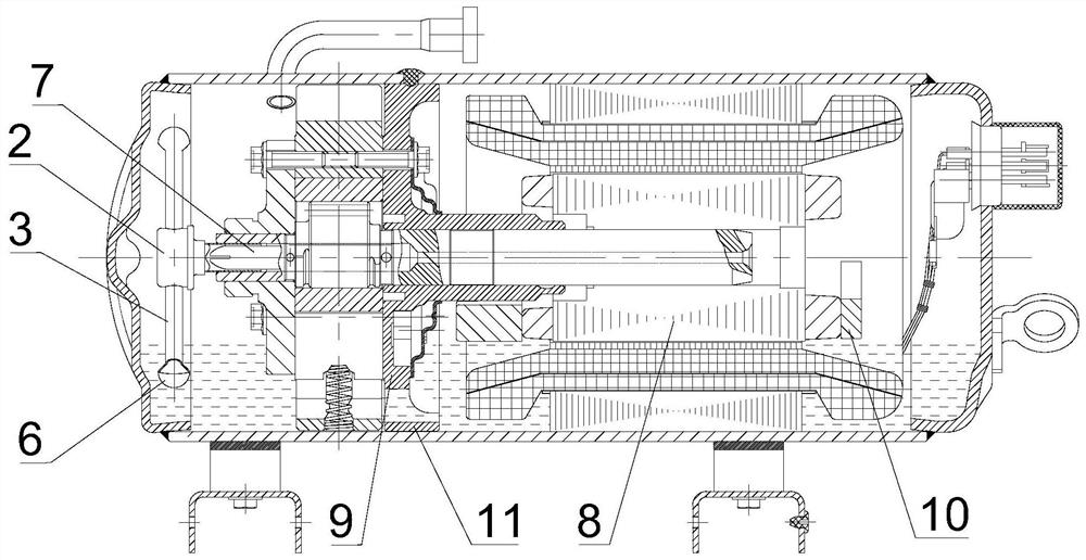
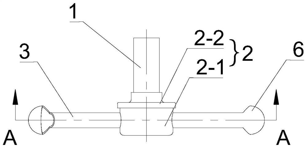
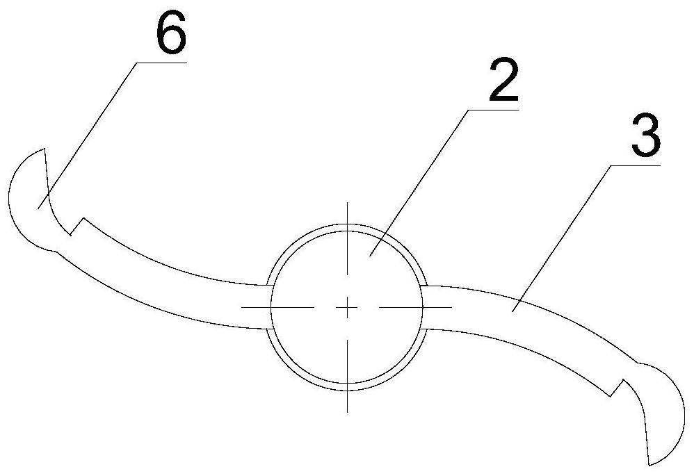
[0034] see Figure 1-6 , the compressor in this embodiment includes a rotary oiling device, the rotary oiling device includes a transmission oil pipe 1, an oil cover 2 and an oil supply pipe 3, one end of the intermediate transmission oil pipe 1 is fixedly connected to the crankshaft, and the other One end is connected to the inner cavity of the upper oil cover 2; the intermediate transition oil pipe 4 is fixed inside the upper oil cover 2, and the inner cavity of the intermediate transition oil pipe 4 is provided with a sealing ball 5, and the intermediate transition oil pipe 4 is provided with multiple two oil passage holes 4-1; the upper oil pipe 3 is provided with two, and the ...


PUM


Abstract

The invention discloses a rotary oiling device and a compressor. The rotary oiling device comprises a transmission oil pipe, an oiling cover and oiling pipes, wherein one end of a middle transmissionoil pipe is coaxially and fixedly connected with a crankshaft of the compressor, and the other end of the middle transmission oil pipe communicates with an inner cavity of the oiling cover; a middle transition oil pipe is fixedly arranged in the oiling cover, a sealing ball is arranged in an inner cavity of the middle transition oil pipe, and an oil passing hole is formed in the middle transitionoil pipe; the number of the oiling pipes is two, and the two oiling pipes are symmetrically arranged; one ends of the two oiling pipes respectively penetrate through the upper oil cover to communicatewith two ends of the middle transition oil pipe, and the other ends of the two oiling pipes are respectively connected with oiling spoons for scooping up refrigeration oil from an oil pool of the compressor; the two oiling spoons are arranged in a central symmetry manner; and the diameter of the sealing ball is larger than that of the oiling pipe. By adopting the rotary oiling device of the invention, parts such as a fan and a baffle plate are removed, so that the cost is reduced; and a vertical rotor and an auxiliary balance block are universal for the rotary oiling device, the universalityis good, and the development and mass production periods of a horizontal compressor are shortened.

Description

technical field [0001] The invention relates to a compressor oiling device, in particular to a rotary oiling device and a compressor. Background technique [0002] At present, in order to meet the oil supply requirements of the horizontal rotor compressor, compared with the vertical compressor, the oil pipe assembly, oil baffle plate, fan and other parts are added. When working, the crankshaft of the horizontal compressor does not extend into the oil pool, and the upper oil pipe assembly needs to be extended into the oil pool. Due to the pumping effect of the oil guide plate in the short shaft of the rotating crankshaft, the gas in the short shaft of the crankshaft and the upper oil cover is drawn out , a certain degree of vacuum is formed at the oil hole of the short shaft of the crankshaft, and a double pressure difference is formed through the fan and the oil baffle, so that the refrigerating machine oil enters the oil cover along the oil pipe, and then is sent to the pum...

Claims


Application Information

Patent Timeline
Patent Type & Authority Applications(China)
IPC IPC(8): F04C29/02
CPCF04C29/02
Inventor 郑仲钦
Owner ZHUHAI GREE REFRIGERATION TECH CENT OF ENERGY SAVING & ENVIRONMENTAL PROTECTION
Learn More