
Aero-engine air compressor and vortex reducer assembly

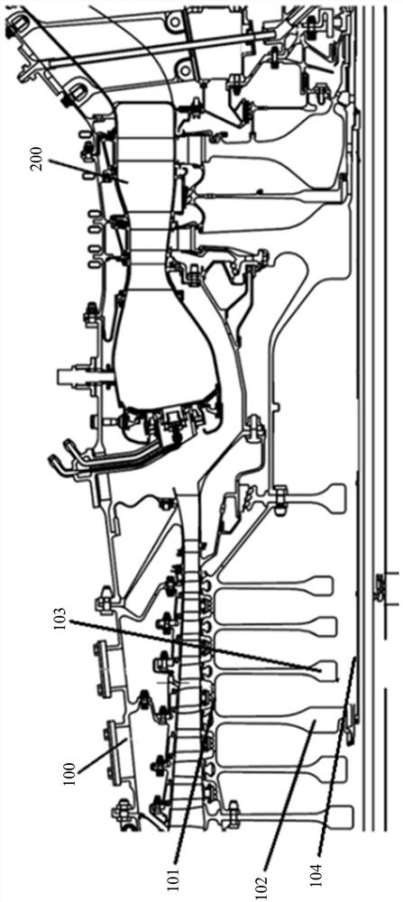
A technology for aero-engines and vortex reducers, which is applied in the direction of machines/engines, liquid fuel engines, pump components, etc., and can solve the problems of poor rigidity, poor surface roughness of the inner wall surface, and difficult machining of inner holes, etc. problems, to achieve the effect of improving the finish, facilitating processing, and improving air-entraining efficiency

Pending Publication Date: 2021-03-16
AECC COMML AIRCRAFT ENGINE CO LTD
View PDF7 Cites 0 Cited by
  • Summary
  • Abstract
  • Description
  • Claims
  • Application Information

AI Technical Summary

Problems solved by technology

In the actual processing process, the vortex reducer is mostly obtained by bar or forging machine. The rigidity of the slender thin-walled tube is poor, the processing of the inner hole is difficult, the precision is low, the surface roughness of the inner wall is poor, and the processing cost is high.
At the same time, the inner wall of the damping tube is the flow channel for cooling the bleed air, and the poor surface roughness will reduce the bleed air efficiency
In addition, the damping tube has grooves along the axial direction on the tube wall, which will also reduce the efficiency of air induction.

Method used


Image

  • Aero-engine air compressor and vortex reducer assembly
  • Aero-engine air compressor and vortex reducer assembly
  • Aero-engine air compressor and vortex reducer assembly

Examples


Embodiment Construction

[0031] The present invention will be further described below in conjunction with specific embodiments and accompanying drawings. In the following description, more details are set forth in order to fully understand the present invention, but the present invention can obviously be implemented in a variety of other ways different from this description, Those skilled in the art can make similar promotions and deductions based on actual application situations without violating the connotation of the present invention, so the content of this specific implementation manner should not limit the protection scope of the present invention.

[0032] For example, the description that the first feature described later in the description is formed on or above the second feature may include the embodiment in which the first and second features are formed through direct contact, and may also include an embodiment in which the first and second features are formed. Embodiments that form addition...


PUM


Abstract

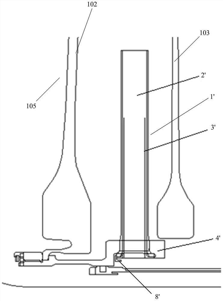
The invention provides a vortex reducer assembly which is used for an aero-engine air compressor. A vortex reducing pipe comprises a fixing end and a free end, the vortex reducing pipe is fixed through the fixing end, and a damping pipe is connected with the free end of the vortex reducing pipe through a threaded pair. The invention further provides the aero-engine air compressor which comprises the vortex reducer assembly. The provided vortex reducer assembly can replace an existing vortex reducer assembly and is convenient to machine or assemble.

Description

technical field [0001] The invention relates to an aero-engine compressor, in particular to a vortex reducer assembly for an aero-engine compressor. Background technique [0002] The working temperature of turbofan engine turbine components is high and the working environment is harsh, especially parts such as high-pressure turbine blades are directly exposed to gas, and the working environment temperature even exceeds the allowable temperature of the material. In order to reduce the working temperature of parts such as turbine rotor blades and ensure the safety of the engine, it is necessary to introduce cooling gas from the high-pressure compressor to cool parts such as turbine rotor blades. The cooling gas of the high-pressure compressor first flows from the main channel through the radial holes on the drum between the adjacent two-stage disks into the adjacent two-stage disk cavity, and then flows to the turbine through the air duct to cool the turbine. Since the rotati...

Claims


Application Information

Patent Timeline
IPC IPC(8): F04D29/66
CPCF04D29/668
Inventor 张辉司武林周超羡郭雅妮魏铭瑛瞿诗云
Owner AECC COMML AIRCRAFT ENGINE CO LTD
Learn More