
Projection Distortion Correction Method, System and Medium in Optical Surface Compensation Interferometry

An interferometric measurement and distortion correction technology, applied in the field of projection distortion correction, can solve problems such as poor results and distortion correction errors, and achieve the effects of high precision, high efficiency and simple calculation method

Active Publication Date: 2022-03-15
NAT UNIV OF DEFENSE TECH
View PDF0 Cites 0 Cited by
  • Summary
  • Abstract
  • Description
  • Claims
  • Application Information

AI Technical Summary

Problems solved by technology

In fact, the abscissa on the optical surface of the compensator is still not a linear mapping to the pixel coordinates on the image surface of the interferometer, resulting in incorrect or ineffective distortion correction

Method used


Image

  • Projection Distortion Correction Method, System and Medium in Optical Surface Compensation Interferometry
  • Projection Distortion Correction Method, System and Medium in Optical Surface Compensation Interferometry
  • Projection Distortion Correction Method, System and Medium in Optical Surface Compensation Interferometry

Examples


Embodiment Construction

[0039] The projection distortion correction method, system and medium in the optical surface shape compensation interferometry of the present invention will be further described in detail below with an example of CGH compensation interferometry of an aspheric surface. The surface to be tested is an ellipsoid with a vertex curvature radius of 691.1 mm and a quadratic constant k=-0.9911. The aperture is φ470 mm, and the diameter of the central blocking hole is 100 mm.

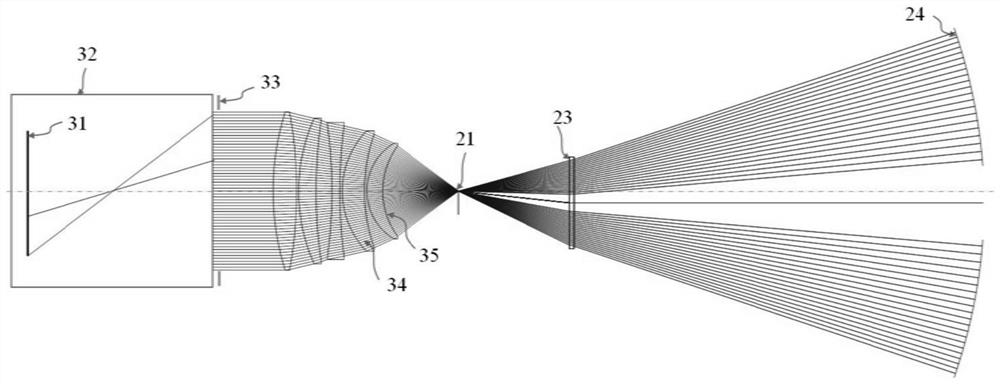
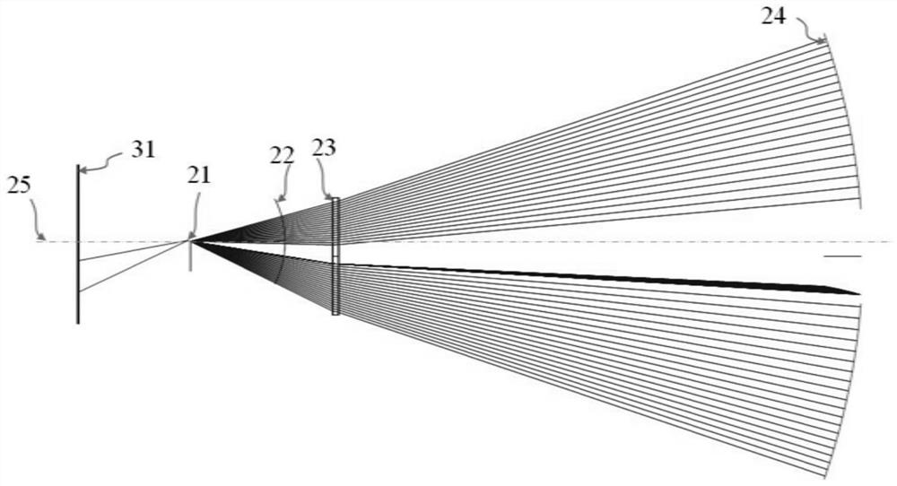
[0040] Such as figure 1 As shown, a spherical wave interferometer 32 is used to configure a spherical lens 34 and a compensator 23 (CGH compensator) to perform compensation interferometry of the ellipsoidal mirror shape, and the measurement result is the surface corresponding to the pixel coordinates on the image plane 31 of the interferometer shape error distribution. The pixel coordinates are in a linear mapping relationship with the last surface on the spherical lens 34 , that is, the abscissa on the spherica...


PUM


Abstract

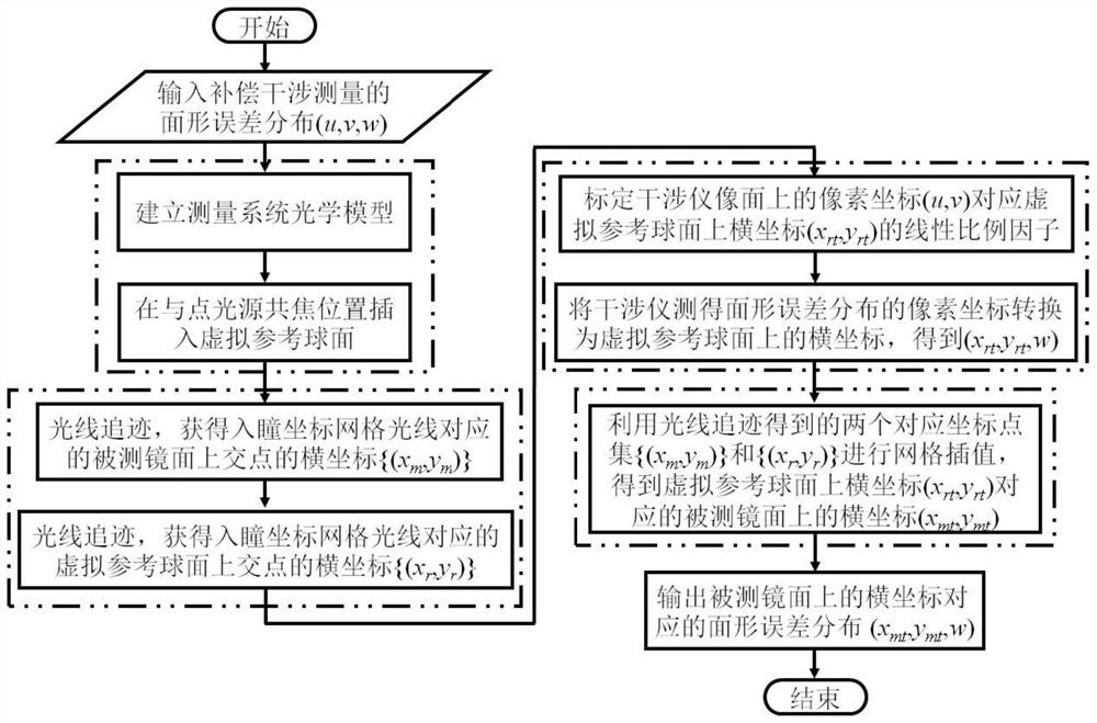
The invention discloses a projection distortion correction method, system and medium in optical surface shape compensation interferometry. The projection distortion correction method of the invention includes: establishing an optical model of the measurement system, and inserting a virtual reference spherical surface at a confocal position with a point light source ; Perform ray tracing to obtain the abscissa {(x m ,y m )} and the abscissa {(x r ,y r )}; The pixel coordinates (u, v) on the image plane of the calibrated interferometer correspond to the abscissa coordinates on the virtual reference sphere (x rt ,y rt ), transform the pixel coordinates of the surface shape error distribution measured by the interferometer into the abscissa on the virtual reference sphere (x rt ,y rt ); perform distortion correction to get the result. The invention does not need to use physical mark point sequences, does not need to perform function fitting on distortion, and has the advantages of simple calculation method, high efficiency and high precision.

Description

technical field [0001] The invention relates to optical surface shape interferometry technology, in particular to a projection distortion correction method, system and medium in optical surface shape compensation interferometry. Background technique [0002] Optical surfaces such as aspheric surfaces, off-axis aspheric surfaces, and free-form surfaces deviate from the ideal spherical shape. When using a wave surface interferometer for interferometric measurement, it is necessary to use a compensator for aberration compensation, which is equivalent to the standard spherical wave emitted by the interferometer. Transformation into an aspheric wave matching the measured mirror surface leads to complex nonlinear mapping between the pixel coordinates of the surface shape error distribution measured by the interferometer and the abscissa on the measured mirror surface. The abscissa on the measured mirror surface can no longer be calibrated with a linear scale factor like the measur...

Claims


Application Information

Patent Timeline
Patent Type & Authority Patents(China)
IPC IPC(8): G01B9/02055
CPCG01B9/02
Inventor 陈善勇戴一帆胡皓关朝亮翟德德熊玉朋薛帅
Owner NAT UNIV OF DEFENSE TECH
Learn More