
Eureka
For R&D, Eureka makes reading and utilizing patents & technical documents easy.
Eureka AIR
Designed for self-driven R&D workflows. Generate viable solutions, solve complex R&D challenges, empower your innovation with AI.

Eureka Materials
Designed for material experts only. Revolutionize your material R&D, from search, analyze, to developing new materials.

TechResearch
Generate reliable direction feasibility study reports for your R&D in just a few steps.

TechSeek
Discover and master advanced knowledge NOW. Basics, ideas, possibilities, all at once.

TechMind
As an expert in R&D Theories, TechMind can generates customized viable solutions instantly.

TechRisk
Analyze your overall solution with one click, know your potential R&D risks in advance.

TechMonitor
Get weekly tech updates, stay abreast of the latest tech innovations and key insights.
Friction sensitivity test mechanical pressurizing device
A technology of mechanical pressurization and friction sensitivity, which is applied in the fields of remote precise pressure control and pressurization devices with protective facilities, friction sensitivity test mechanical pressurization devices, and can solve the problems of poor repeatability of pressure control, easy oil leakage of hydraulic machines, and poor pressure. Stability and other issues, to achieve precise and stable pressure control, eliminate oil pollution, and simplify the pressurization process
- Summary
- Abstract
- Description
- Claims
- Application Information
AI Technical Summary
Problems solved by technology
Method used
Image

Examples
Embodiment 1
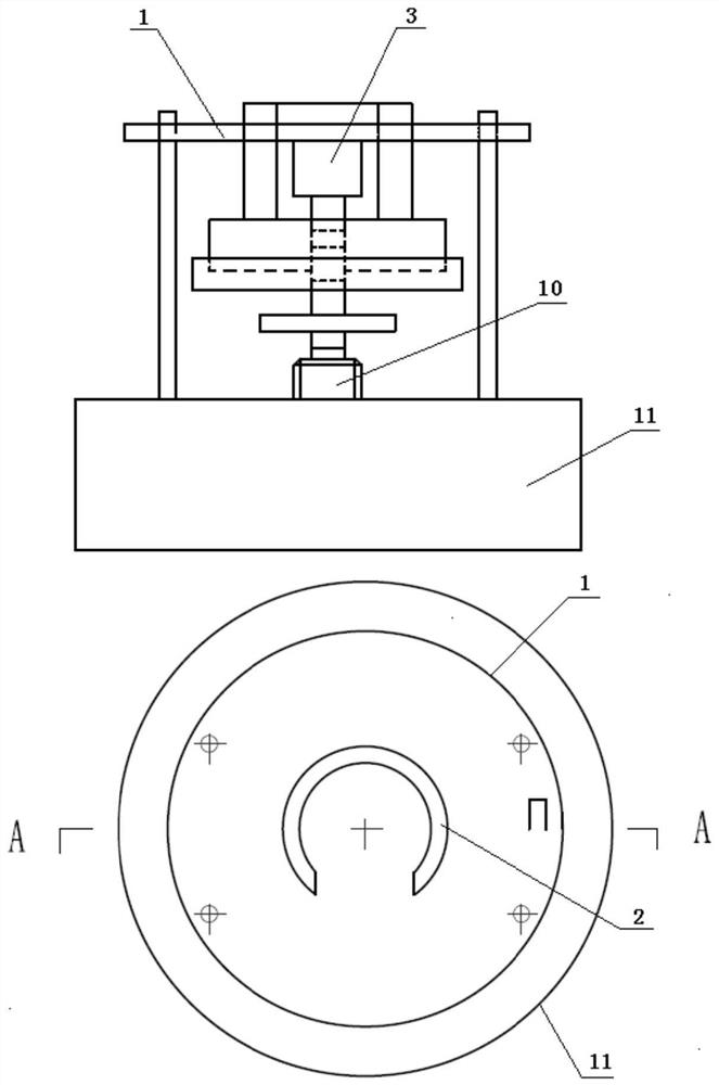
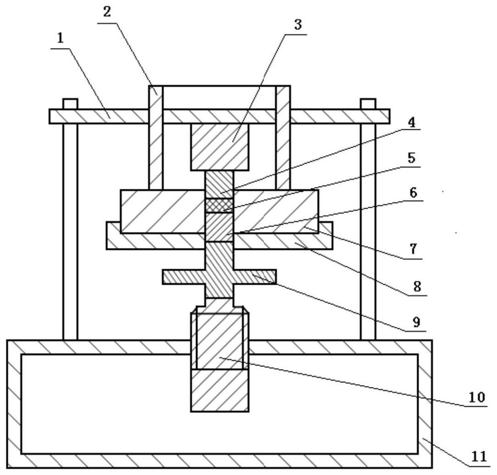
[0046] Such as Figure 1 to Figure 5 As shown, this embodiment provides a friction-sensitive mechanical pressing device. It is characterized in that it includes a reaction chamber 1, a pressure sleeve 2, an upper ejector 3, an upper plunger 4, a sample 5, a lower plunger 6, a plunger sleeve 7, a lower top sleeve 8, an ejector rod 9, and a servo press 10 and rack 11;
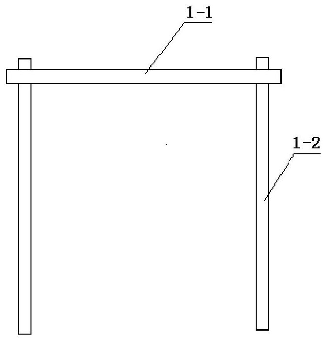
[0047] The reaction chamber 1 is composed of a top plate 1-1 and a column 1-2, and the top plate 1-1 is fixedly installed on the top of the frame 11 through four columns 1-2 to form a semi-open chamber;
[0048] The pressure sleeve 2 is a fan-shaped ring, installed on the top plate 1-1, and can move up and down under the action of the cylinder, and forms a semi-open circular chamber with the stud sleeve 7 after being pressed down;
[0049] The upper top column 3 is a cylindrical structure, located in the center of the inner side of the pressure sleeve 2, and fixedly installed under the top plate 1-1;
[0050] ...
Embodiment 2
[0077] Such as Figure 1 to Figure 5 As shown, this embodiment provides a friction-sensitive mechanical pressing device. It is characterized in that it includes a reaction chamber 1, a pressure sleeve 2, an upper ejector 3, an upper plunger 4, a sample 5, a lower plunger 6, a plunger sleeve 7, a lower top sleeve 8, an ejector rod 9, and a servo press 10 and rack 11;
[0078] The reaction chamber 1 is composed of a top plate 1-1 and a column 1-2, and the top plate 1-1 is fixedly installed on the top of the frame 11 through four columns 1-2 to form a semi-open chamber;
[0079] The pressure sleeve 2 is a fan-shaped ring, installed on the top plate 1-1, and can move up and down under the action of the cylinder, and forms a semi-open circular chamber with the stud sleeve 7 after being pressed down;
[0080] The upper top column 3 is a cylindrical structure, located in the center of the inner side of the pressure sleeve 2, and fixedly installed under the top plate 1-1;
[0081] ...
PUM
 Abstract
Description
Claims
Application Information
 - R&D Engineer
- R&D Manager
- IP Professional
- Industry Leading Data Capabilities
- Powerful AI technology
- Patent DNA Extraction
Browse by: Latest US Patents, China's latest patents, Technical Efficacy Thesaurus, Application Domain, Technology Topic, Popular Technical Reports.
© 2024 PatSnap. All rights reserved.Legal|Privacy policy|Modern Slavery Act Transparency Statement|Sitemap|About US| Contact US: help@patsnap.com