
Eureka
For R&D, Eureka makes reading and utilizing patents & technical documents easy.
Eureka AIR
Designed for self-driven R&D workflows. Generate viable solutions, solve complex R&D challenges, empower your innovation with AI.

Eureka Materials
Designed for material experts only. Revolutionize your material R&D, from search, analyze, to developing new materials.

TechResearch
Generate reliable direction feasibility study reports for your R&D in just a few steps.

TechSeek
Discover and master advanced knowledge NOW. Basics, ideas, possibilities, all at once.

TechMind
As an expert in R&D Theories, TechMind can generates customized viable solutions instantly.

TechRisk
Analyze your overall solution with one click, know your potential R&D risks in advance.

TechMonitor
Get weekly tech updates, stay abreast of the latest tech innovations and key insights.
Lithium ion battery diaphragm cutting and positioning device
A lithium-ion battery and positioning device technology, which is applied to secondary batteries, battery pack components, non-aqueous electrolyte batteries, etc., can solve the problems of low safety, low pass rate, and low efficiency of manual cutting, and reduce manpower Consumption, improve the qualified rate and efficiency, improve the effect of production efficiency
- Summary
- Abstract
- Description
- Claims
- Application Information
AI Technical Summary
Problems solved by technology
Method used
Image

Examples
Embodiment 1
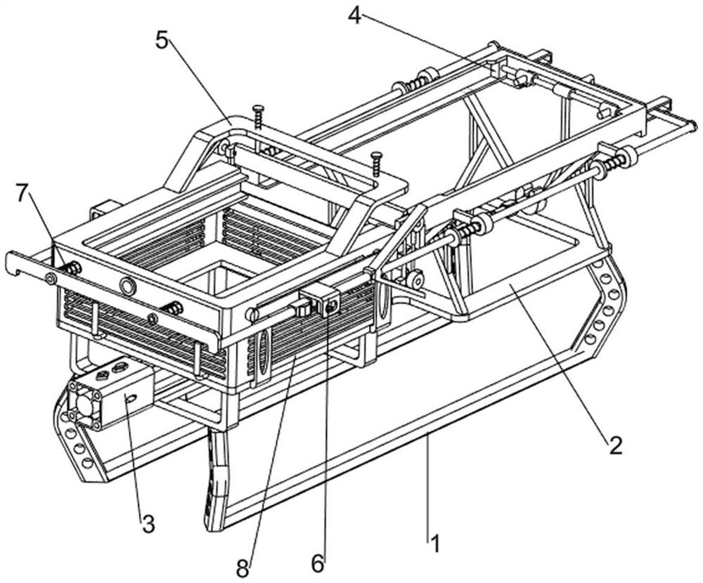
[0067] A lithium-ion battery diaphragm cutting positioning device, such asfigure 1 and figure 2 As shown, it includes a base 1, a working frame 2, a pulling mechanism 3, a sliding mechanism 4 and a cutting mechanism 5. The middle part of the base 1 is provided with a working frame 2, and the upper side of the working frame 2 is provided with a pulling mechanism 3. A sliding mechanism 4 is provided, and the sliding mechanism 4 is connected with the pulling mechanism 3. The front part of the working frame 2 is provided with a cutting mechanism 5, and the cutting mechanism 5 cooperates with the sliding mechanism 4.
[0068] When people are ready to cut off the lithium battery diaphragm, the lithium battery is placed in the sliding mechanism 4 first, and the pulling mechanism 3 is started at this time, the pulling mechanism 3 will drive the sliding mechanism 4 to move forward, and the sliding mechanism 4 will drive the lithium battery to move forward In the cutting mechanism 5, t...
Embodiment 2
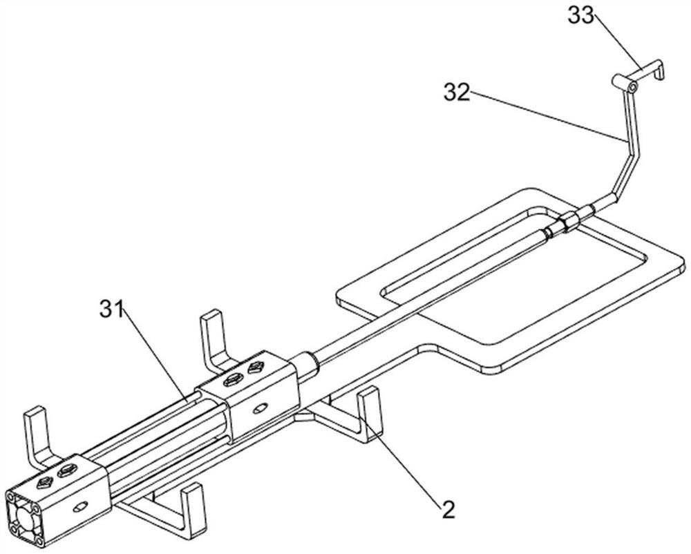
[0070] On the basis of Example 1, such as figure 1 , figure 2 , image 3 , Figure 4 , Figure 5 , Figure 8 and Figure 9 As shown, the pulling mechanism 3 includes a cylinder 31, a first connecting rod 32 and a first connecting block 33, and the upper side of the front part of the work frame 2 is equipped with a cylinder 31, and the cylinder 31 is provided with a first connecting rod 32, and the first connecting rod 32 is provided with a first connection block 33 on the top.
[0071] When people are ready to cut off the lithium battery diaphragm, the lithium battery is first placed in the sliding mechanism 4, and the cylinder 31 is started at this time, and the cylinder 31 will drive the first connecting rod 32 to move forward, and the first connecting rod 32 will drive the first connecting rod 32 to move forward. The block 33 moves forward, and the first connecting block 33 will drive the sliding mechanism 4 to move forward, and the sliding mechanism 4 will drive the...
Embodiment 3
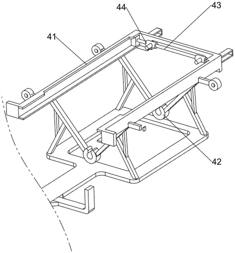
[0077] On the basis of Example 2, such as figure 1 , Figure 5 , Figure 6 , Figure 7 , Figure 8 and Figure 9 As shown, it also includes a blanking mechanism 6, and the blanking mechanism 6 includes a second pull rod 61, a fifth connecting rod 62, an extruding block 63, a second connecting block 64, a fourth compression spring 65, and a third connecting block 66 , rotating block 67 and torsion spring 68, the special-shaped block 511 front portions on the left and right sides are provided with the second pull rod 61, the fifth connecting rod 62 is provided at the front portion of the second pull rod 61, and the middle part of the second pull rod 61 is provided with extruding Block 63, the left and right sides of the material storage frame 51 are all slidingly connected with the second connecting block 64, and the second connecting block 64 is wound with two fourth compression springs 65, and the fourth compression spring 65 is connected with the material storage frame 51...
PUM
 Abstract
Description
Claims
Application Information
 - R&D Engineer
- R&D Manager
- IP Professional
- Industry Leading Data Capabilities
- Powerful AI technology
- Patent DNA Extraction
Browse by: Latest US Patents, China's latest patents, Technical Efficacy Thesaurus, Application Domain, Technology Topic, Popular Technical Reports.
© 2024 PatSnap. All rights reserved.Legal|Privacy policy|Modern Slavery Act Transparency Statement|Sitemap|About US| Contact US: help@patsnap.com