Blind cavity structure interference assembly rotor cold assembly elastic guide device for assembly
A guiding device and rotor technology, applied in electromechanical devices, manufacture of stator/rotor body, manufacture of motor generators, etc., can solve problems such as easy to bruise internal parts, internal damage cannot be found, quality problems in assembly process, etc., to achieve Improve quality and efficiency, save production costs, and reduce the effect of assembly cycle
- Summary
- Abstract
- Description
- Claims
- Application Information
AI Technical Summary
Problems solved by technology
Method used
Image

Examples
Embodiment Construction
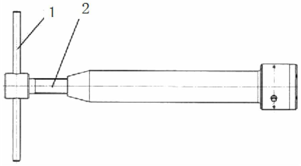
[0020] Such as Figure 1-4 As shown, the technical solution starts from the structure of the shaft end of the low-pressure turbine rotor and the internal structure of the core machine of the whole machine. The moving pin switching and pressing scheme makes the guide device more convenient in the process of quick assembly, firm fixation, assembly guidance, and quick disassembly.
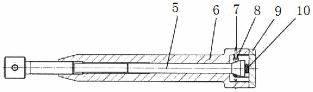
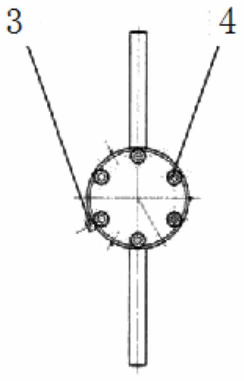
[0021] An elastic guide device for cold assembly of a blind cavity structure interference assembly rotor, including a handle 1, a screw rod 2, a stop pin 3, a hexagon socket head screw 4, a mandrel 5, a guide shaft 6, a stop pin 7, and a small compression spring Foot 8, cover plate 9, large compression spring 10;
[0022] The guide shaft 6 is a main structural part, which is a hollow tubular structure. The right end has a large diameter and a step. Its large diameter is matched with the internal control large radial direction of the low-pressure turbine shaft end 11, and there are 3 radial fixing hol...
PUM
 Abstract
Description
Claims
Application Information
 - R&D
- Intellectual Property
- Life Sciences
- Materials
- Tech Scout
- Unparalleled Data Quality
- Higher Quality Content
- 60% Fewer Hallucinations
Browse by: Latest US Patents, China's latest patents, Technical Efficacy Thesaurus, Application Domain, Technology Topic, Popular Technical Reports.
© 2025 PatSnap. All rights reserved.Legal|Privacy policy|Modern Slavery Act Transparency Statement|Sitemap|About US| Contact US: help@patsnap.com