Constant-temperature and constant-humidity air treatment equipment and method

An air treatment, constant temperature and humidity technology, applied in separation methods, chemical instruments and methods, and dispersed particle filtration, can solve problems such as unfavorable energy saving, energy waste, and inability to meet drastic changes in temperature and humidity, and achieve stable air supply temperature. Effect

Inactive Publication Date: 2021-03-19
威海众海智能科技有限公司
View PDF8 Cites 2 Cited by
  • Summary
  • Abstract
  • Description
  • Claims
  • Application Information

AI Technical Summary

Problems solved by technology

Because laboratories with this requirement usually need to run continuously for 24 hours, and there are even changes in indoor temperature and humidity requirements. Conventional constant temperature and humidity equipment will cause a lot of waste of energy and cannot meet their needs for drastic changes in temperature and humidity.
[0003] Many laboratories in the industry have relatively high-precision control requirements for indoor temperature and humidity (such as 25±1°C, 40±4%). Because of the high control acc

Method used


Image

  • Constant-temperature and constant-humidity air treatment equipment and method
  • Constant-temperature and constant-humidity air treatment equipment and method
  • Constant-temperature and constant-humidity air treatment equipment and method

Examples


Embodiment Construction

[0030]The following will clearly and completely describe the technical solutions in the embodiments of the present invention with reference to the accompanying drawings in the embodiments of the present invention. Obviously, the described embodiments are only some, not all, embodiments of the present invention.

[0031] In describing the present invention, it should be understood that the terms "upper", "lower", "front", "rear", "left", "right", "top", "bottom", "inner", " The orientation or positional relationship indicated by "outside", etc. is based on the orientation or positional relationship shown in the drawings, and is only for the convenience of describing the present invention and simplifying the description, rather than indicating or implying that the referred device or element must have a specific orientation, so as to Specific orientation configurations and operations, therefore, are not to be construed as limitations on the invention.

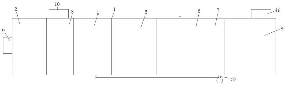
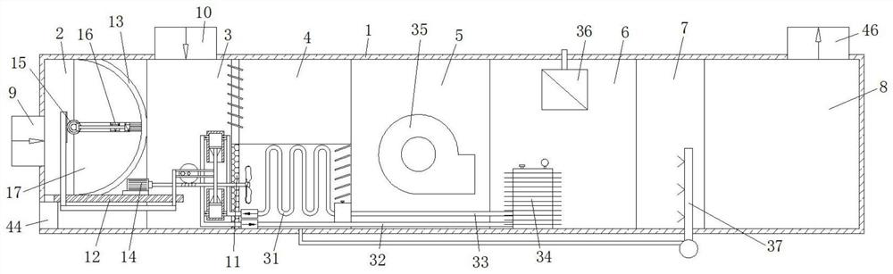
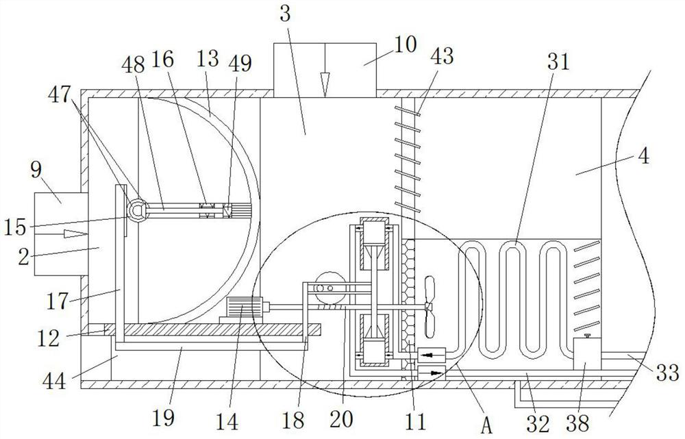
[0032] refer to Figure 1...


PUM


Abstract

The invention relates to the technical field of air treatment, and discloses constant-temperature and constant-humidity air treatment equipment and method. The equipment comprises a bin body, and a fresh air filtering cavity, a mixing cavity, a cooling and dehumidifying cavity, a fan cavity, a heating cavity, a humidifying cavity and a mixed air supply cavity which are sequentially arranged in thebin body from left to right, a fresh air inlet is arranged at the left side of the fresh air filtering cavity, an air return inlet is formed in the top side of the mixing cavity, an air supply outletis formed in the top side of the mixing air supply cavity, a pore plate is fixedly connected between the mixing cavity and the cooling and dehumidifying cavity, a bearing table is fixedly connected to the bottom of the inner side of the fresh air filtering cavity, a semispherical filtering cover and a motor are fixedly connected to the two sides of the top of the bearing table correspondingly, agear is rotationally connected into the fresh air filtering cavity, and a horizontally-arranged supporting plate is fixedly connected to the outer side of the gear. By means of the design, the effectsof heat recovery and water resource cyclic utilization are achieved, the purpose of saving energy is achieved through segmented control, the temperature gradient is reduced through charging and mixing before air supply, and the temperature and humidity are constant, reliable and easy to control.

Description

technical field [0001] The invention relates to the technical field of air treatment, in particular to a constant temperature and humidity air treatment equipment and method. Background technique [0002] Conventional constant temperature and humidity air treatment equipment configures cooling and dehumidification facilities according to the circulating air volume. Because of the correlation between temperature and humidity, a large amount of air needs to be treated to the dew point (condensation) to solve the dehumidification problem, and the machine dew point (condensation) The temperature is very low, so after cooling, it needs to be heated up by reheating to ensure the constant temperature and relative humidity. Because laboratories with this requirement usually need to run 24 hours a day without interruption, and there may even be changes in indoor temperature and humidity requirements, conventional constant temperature and humidity equipment will cause a lot of waste o...

Claims


Application Information

Patent Timeline
IPC IPC(8): B01D46/10B01D46/00B01D53/26
CPCB01D46/103B01D53/265B01D46/681
Inventor 张爱英
Owner 威海众海智能科技有限公司
Why Eureka
Try Eureka