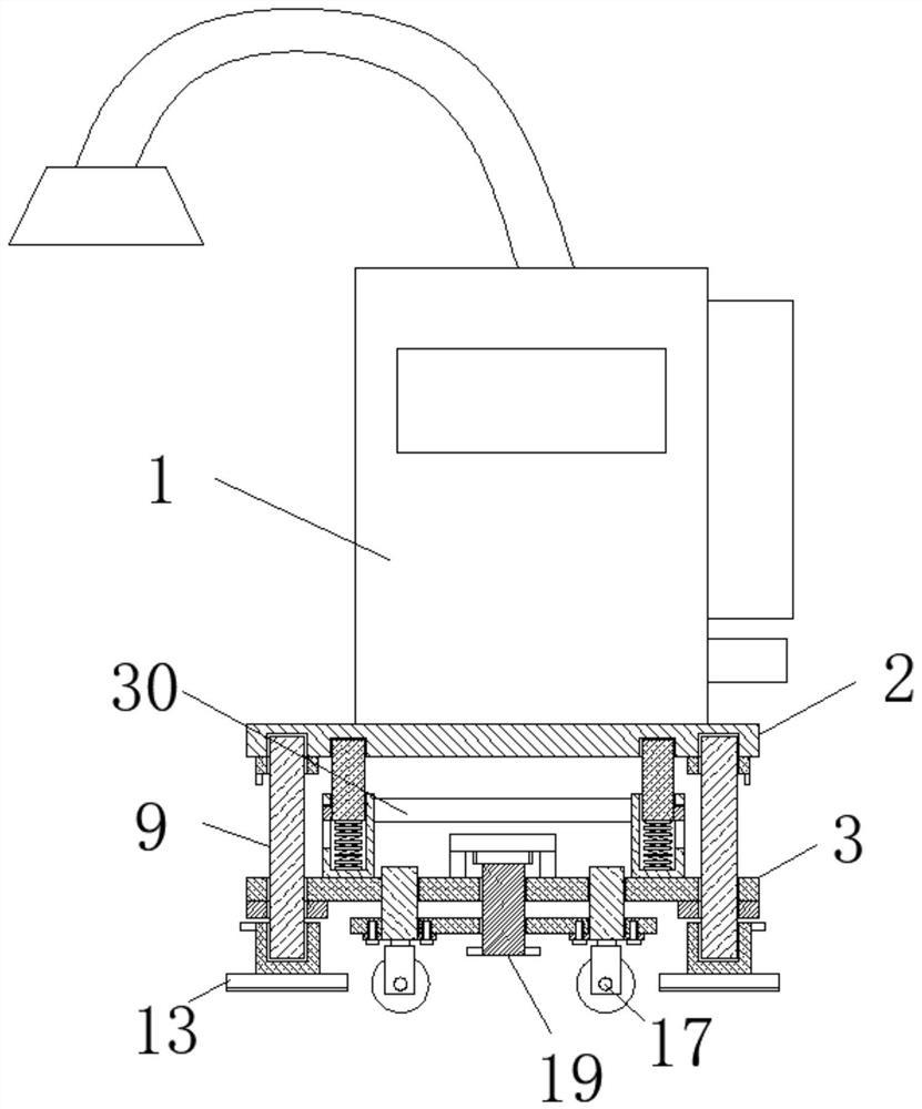
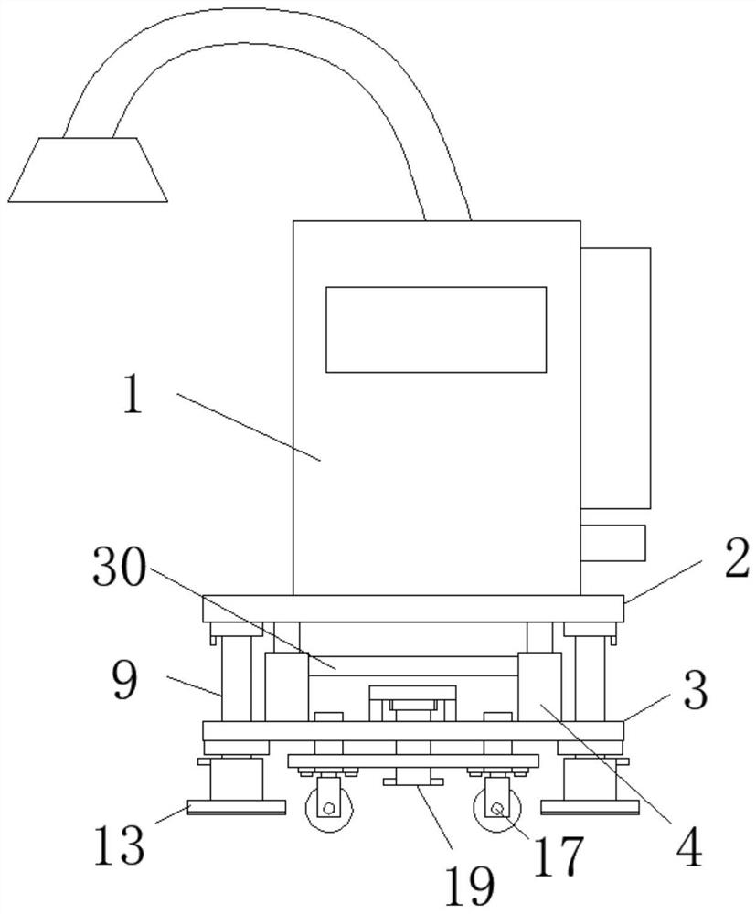
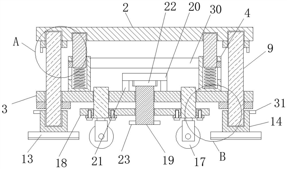
Movable waste gas treatment equipment

A waste gas treatment and mobile technology, applied in the direction of smoke removal, cleaning methods and appliances, chemical instruments and methods, etc., can solve problems such as unorganized emissions, different space required, environmental pollution, etc., and achieve easy replacement and rotation , reducing the effect of sliding

Inactive Publication Date: 2021-03-19
湘潭华悦电子科技有限公司
View PDF2 Cites 0 Cited by
  • Summary
  • Abstract
  • Description
  • Claims
  • Application Information

AI Technical Summary

Problems solved by technology

[0003] The main purpose of the present invention is to provide a mobile waste gas treatment equipment, which can effectively solve the problem that in the background technology, the suction effect will be weakened if the height exceeds a certain height, and some organic waste gas will not be able to be adsorbed, resulting in unorganized discharge into the atmosphere. The space required for different filling operations is different, resulting in different heights of the fixed suction hood, which affects the overall layout planning of the workshop. If the suction hood is installed uniformly, once the filling container is placed in the wrong position, there will be waste gas that is not absorbed by the suction hood. It is free and unorganized emission into the atmosphere, which leads to the problem of environmental pollution

Method used


Image

  • Movable waste gas treatment equipment
  • Movable waste gas treatment equipment
  • Movable waste gas treatment equipment

Examples


Embodiment Construction

[0022] In order to make the technical means, creative features, goals and effects achieved by the present invention easy to understand, the present invention will be further described below in conjunction with specific embodiments.

[0023] In the description of the present invention, it should be noted that the terms "upper", "lower", "inner", "outer", "front end", "rear end", "both ends", "one end", "another end" The orientation or positional relationship indicated by etc. is based on the orientation or positional relationship shown in the drawings, and is only for the convenience of describing the present invention and simplifying the description, rather than indicating or implying that the referred device or element must have a specific orientation, use a specific Azimuth configuration and operation, therefore, should not be construed as limiting the invention. In addition, the terms "first" and "second" are used for descriptive purposes only, and should not be understood ...


PUM


Abstract

The invention discloses movable waste gas treatment equipment which comprises a waste gas treatment equipment body. An equipment base is fixedly connected to the bottom of the waste gas treatment equipment body, a supporting buffer plate is arranged below the equipment base, and two first supporting plates are arranged at the top of the supporting buffer plate. The bottom of the first supporting plate makes contact with the top of the supporting buffer plate, a first sliding groove is formed in the top of the first supporting plate, a sliding plate is arranged in the first sliding groove, thetop end of the sliding plate extends out of the first sliding groove, two positioning grooves are formed in the bottom of the equipment base, and the top end of the sliding plate is located in the positioning grooves. The movable waste gas treatment equipment belongs to the technical field of waste gas adsorption equipment manufacturing, and aims at conveniently driving a waste gas treatment equipment body to move freely, flexibly switching multiple stations, conveniently replacing a spring along with the increase of service time and the reduction of the elastic force of the spring, and facilitating actual use.

Description

technical field [0001] The invention relates to the technical field of waste gas adsorption equipment manufacturing, in particular to a mobile waste gas treatment equipment. Background technique [0002] Chemical, machinery, electronics, electrical appliances, coating, shoemaking, rubber, plastic, printing, medicine, packaging and other production processes will produce organic waste gas. If these tail gases are not treated and discharged directly into the atmosphere, it will cause environmental damage. Serious pollution. At present, domestic organic waste gas treatment equipment is generally fixed in a certain position in the workshop, and each source of waste gas must be installed with a suction hood, resulting in long air ducts and a large structure for the exhaust gas treatment equipment, which not only improves the exhaust gas treatment effect Not good, but also affect the overall layout of the workshop. Generally, the best position for the adsorption cover of waste ga...

Claims


Application Information

Patent Timeline
IPC IPC(8): B08B15/02
CPCB08B15/02
Inventor 李琴
Owner 湘潭华悦电子科技有限公司
Why Eureka
Try Eureka