Intelligent double-spindle end face milling machine for blade root flange face machining
A face milling machine and face machining technology, applied in the field of intelligent dual-spindle face milling machines, can solve the problems of safety risks, difficult operation, pollution of the production environment, etc., and achieve the effect of automatic milling, wide application range and safe operation.
- Summary
- Abstract
- Description
- Claims
- Application Information
AI Technical Summary
Problems solved by technology
Method used
Image
Examples
Embodiment 1
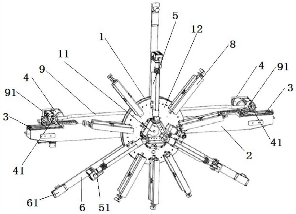
[0046] refer to Figure 1 to Figure 9 As shown, an intelligent dual-spindle face milling machine for blade root flange surface processing includes:
[0047] The slewing bearing 1 is located at the center of the milling machine and includes an inner ring 11, an outer ring 12 and a rotating disc (not shown in the figure), and the rotating disc (not shown in the figure) is fixed on the outer ring 12;
[0048] The beam 2 is fixed on the front of the slewing bearing 1 and arranged along the diameter direction of the flange surface. The outer ring 12 can drive the beam 2 to rotate precisely;
[0049] The slide table 3 is located at both ends of the beam 2 and can move in the X / Y direction;
[0050] The milling cutter spindle 4 is located on the slide table and is equipped with a milling cutter 41 .
[0051] The two ends of the crossbeam 2 are provided with a slide table 3, and the slide table 3 is provided with a milling cutter spindle 4 and a milling cutter 41. The double-spindle...
Embodiment approach
[0059] As another implementation manner of this embodiment, it also includes:
[0060] The lifting tensioning part 5 moves radially along the blade root, one end is connected to the inner ring 11 through the rear flange, and the other end is connected to the positioning support foot 52 through the fine-tuning part 51;
[0061] The positioning leaning member 6 includes three positioning components 61, one end of the positioning component 61 is connected to the outer ring 12 through the front flange, and the other end is provided with an axial pressure sensor 7;
[0062] The axial pressure sensor 7 is located on the positioning plate member 6, facing the flange surface of the blade root to be processed, and is used to detect whether the equipment is parallel to the flange surface of the blade root;
[0063] Fine-tuning part 51 comprises guide rail 53 and motor 54 that axially arranges, and motor drive makes described positioning support foot 52 and lifting tension member 5 produ...
Embodiment 2
[0088] Such as Figure 10 As shown, the system also includes on the basis of Embodiment 1:
[0089] blade root support device 101, for supporting blade root 102 for processing; and
[0090] The protective fence 104, the control cabinet 105, the storage trolley 106 and the dust collector 107 are arranged on the blade root supporting equipment 101 and the milling machine 103 side;
[0091] The protective fence 104 is used to prevent irrelevant personnel from entering the processing area during the processing to prevent accidents; the dust collector 107 absorbs and temporarily stores iron filings and dust generated during the processing.
[0092] The electric wires used on the milling machine 103 are all stretched out from the middle of the beam 2 and connected to the control cabinet 105 .
[0093] Both the control cabinet 105 and the dust collector 107 can be stored on the storage trolley 106, which is convenient for storage and transfer.
[0094] The present invention is mai...
PUM
 Abstract
Description
Claims
Application Information
 - R&D Engineer
- R&D Manager
- IP Professional
- Industry Leading Data Capabilities
- Powerful AI technology
- Patent DNA Extraction
Browse by: Latest US Patents, China's latest patents, Technical Efficacy Thesaurus, Application Domain, Technology Topic, Popular Technical Reports.
© 2024 PatSnap. All rights reserved.Legal|Privacy policy|Modern Slavery Act Transparency Statement|Sitemap|About US| Contact US: help@patsnap.com


