
Welding equipment

A technology of welding equipment and welding parts, applied in welding equipment, laser welding equipment, metal processing equipment, etc., can solve the problems of unguaranteed welding quality, poor welding effect and low efficiency.

Inactive Publication Date: 2021-03-19
SHENZHEN TETELASER TECH CO LTD
View PDF0 Cites 1 Cited by
  • Summary
  • Abstract
  • Description
  • Claims
  • Application Information

AI Technical Summary

Problems solved by technology

[0002] In the manufacturing industry of electronic products, in order to enhance the service life and stability of electronic products, metal parts in electronic components and PCB boards are usually made of copper. Due to the small size of electronic components, there are often many Electronic components are arranged together, when multiple electronic components want to be welded together, there will be a lot of inconvenience
The existing welding method is usually manual welding, the speed of manual welding is slow and the efficiency is low. At the same time, due to the characteristics of copper itself, the welding effect of manual welding is poor, and it is easy to cause welding slag splashing, and the welding quality cannot be guaranteed.

Method used


Image

  • Welding equipment
  • Welding equipment
  • Welding equipment

Examples


Embodiment Construction

[0028] The following will clearly and completely describe the technical solutions in the embodiments of the present invention with reference to the accompanying drawings in the embodiments of the present invention. Obviously, the described embodiments are only part of the embodiments of the present invention, not all of them. Based on the embodiments of the present invention, all other embodiments obtained by persons of ordinary skill in the art without creative efforts fall within the protection scope of the present invention.

[0029] It should be noted that if there is a directional indication (such as up, down, left, right, front, back...) in the embodiment of the present invention, the directional indication is only used to explain the position in a certain posture (as shown in the accompanying drawing). If the specific posture changes, the directional indication will also change accordingly.

[0030] In addition, if there are descriptions involving "first", "second" and ...


PUM


Abstract

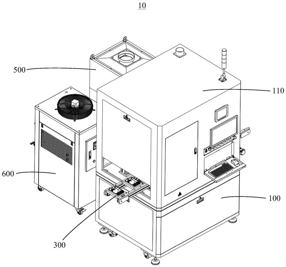
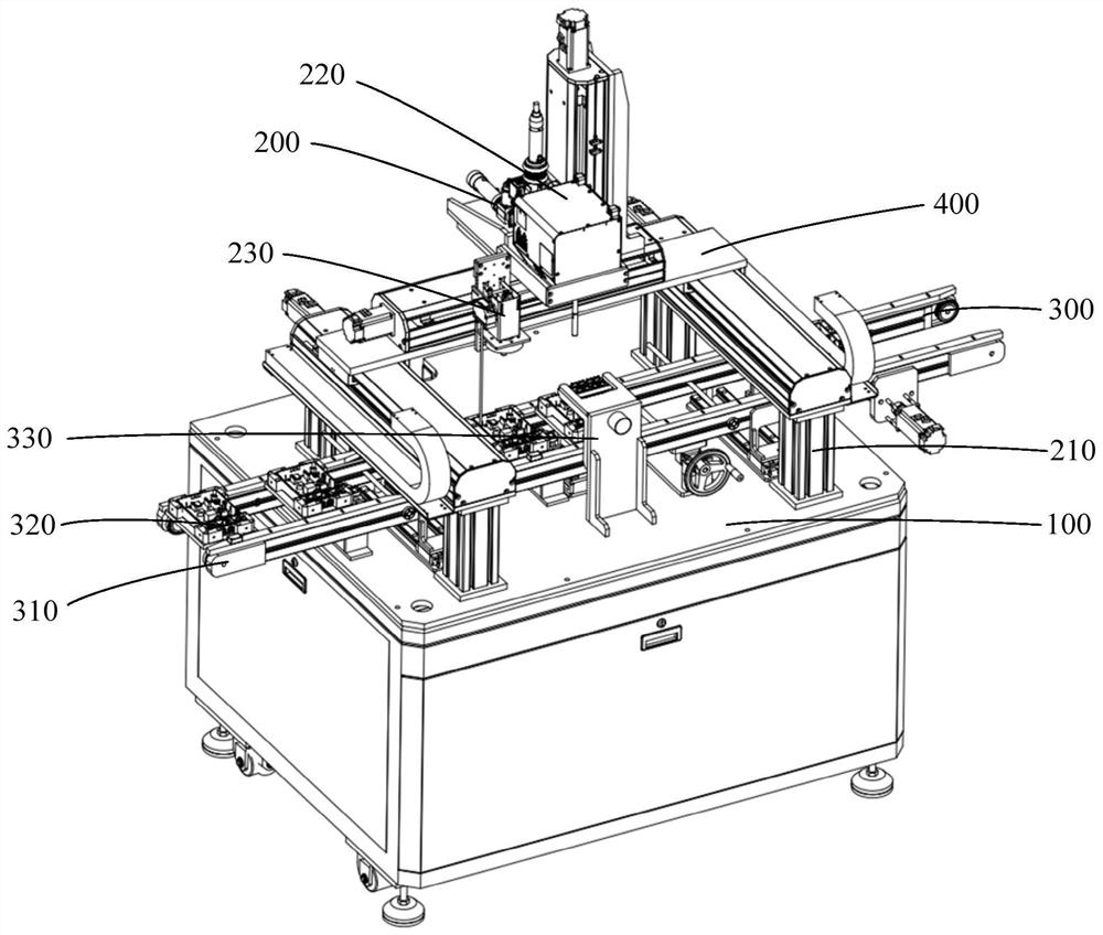
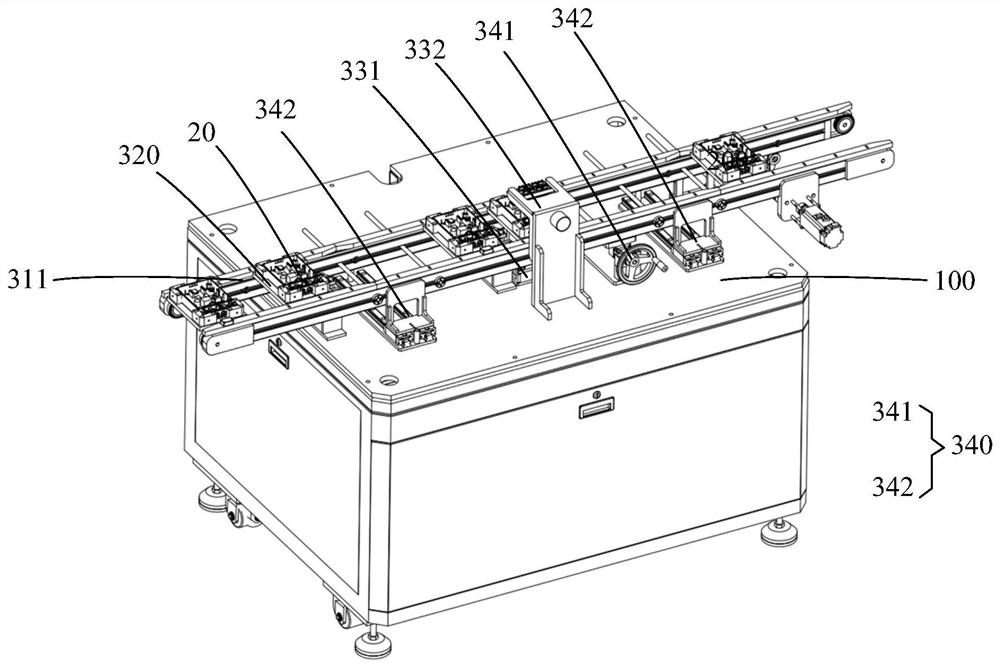
The invention provides welding equipment. The welding equipment comprises a workbench, a welding mechanism and a conveying mechanism. The welding mechanism comprises a portal frame and a green laser.The portal frame is installed on the workbench. The green laser is movably installed on the portal frame. The conveying mechanism is installed on the workbench and comprises a conveying assembly, a fixed carrier and a positioning assembly. The fixed carrier can be used for installing and fixing a to-be-welded piece. The conveying assembly is used for conveying the to-be-welded piece. The fixed carrier is arranged on the conveying assembly and can move along with the conveying assembly. The positioning assembly is used for positioning the fixed carrier on the conveying assembly. The green lasercan weld the to-be-welded piece in the positioned fixed carrier. According to the welding equipment, a function of automatically welding the to-be-welded piece can be fulfilled, so that the welding efficiency of the to-be-welded piece is improved, and the welding quality is ensured.

Description

technical field [0001] The invention relates to the field of welding technology, in particular to a welding device. Background technique [0002] In the manufacturing industry of electronic products, in order to enhance the service life and stability of electronic products, metal parts in electronic components and PCB boards are usually made of copper. Due to the small size of electronic components, there are often many Electronic components are arranged together, and when multiple electronic components want to be welded together, there will be a lot of inconvenience. The existing welding method is usually manual welding, the speed of manual welding is slow and the efficiency is low. At the same time, due to the characteristics of copper itself, the welding effect of manual welding is poor, and it is easy to cause welding slag splashing, and the welding quality cannot be guaranteed. [0003] Therefore, it is necessary to propose a welding device to solve the above problems....

Claims


Application Information

Patent Timeline
IPC IPC(8): B23K26/21B23K26/08B23K26/02B23K26/70
CPCB23K26/02B23K26/083B23K26/21B23K26/702
Inventor 周建阳吴星王庆丰张宏吴华安林克斌周学慧张凯
Owner SHENZHEN TETELASER TECH CO LTD
Learn More