
Machining device for advanced small guide pipe for underground space and hydraulic tunnel

A technology of advanced small conduit and underground space, which is applied in the field of advanced small conduit processing device, can solve the problems of long time consumption, large axial reaction force, damage to internal threads, etc., and achieves increased drilling efficiency, reliable and durable travel, and heating efficiency. multiplier effect

Pending Publication Date: 2021-03-19
YUNNAN CONSTR & INSTALLATION JOINT STOCK
View PDF1 Cites 0 Cited by
  • Summary
  • Abstract
  • Description
  • Claims
  • Application Information

AI Technical Summary

Problems solved by technology

In actual operation, due to the high punching pressure, the clamping part is not stable in clamping the steel pipe, causing the punching position to deviate. The screw jack is easily affected by the radial force and the propulsion direction deviates from the predetermined direction, which requires timely maintenance by the operator. This increases the workload of the operator and prolongs the production time of the small conduit; in addition, in the process of making the cone head, the axial reaction force is relatively large, resulting in damage to the internal thread and making the seamless steel pipe unable to advance
[0004] In addition, the heating process is currently a time-consuming link in the processing of advanced small catheters. The only way to shorten the heating time is to increase the power of the high-frequency heating coil, or to reduce the diameter of the high-frequency heating coil to increase the radiation efficiency, resulting in Increased coil loss, resulting in frequent coil replacement during the production of small catheters

Method used


Image

  • Machining device for advanced small guide pipe for underground space and hydraulic tunnel
  • Machining device for advanced small guide pipe for underground space and hydraulic tunnel
  • Machining device for advanced small guide pipe for underground space and hydraulic tunnel

Examples


Embodiment 1

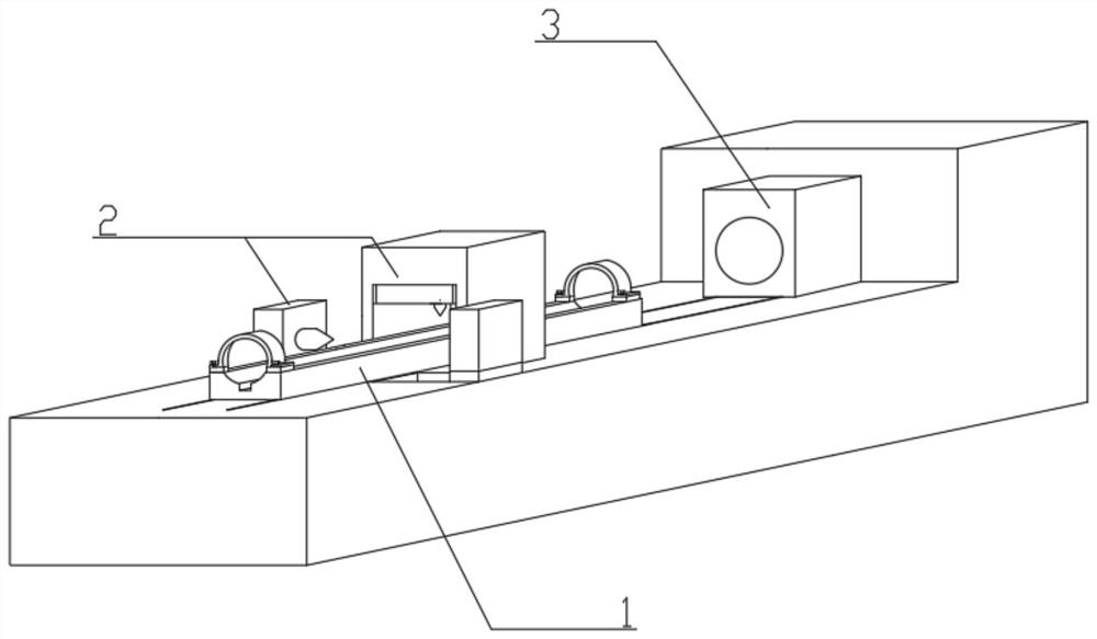
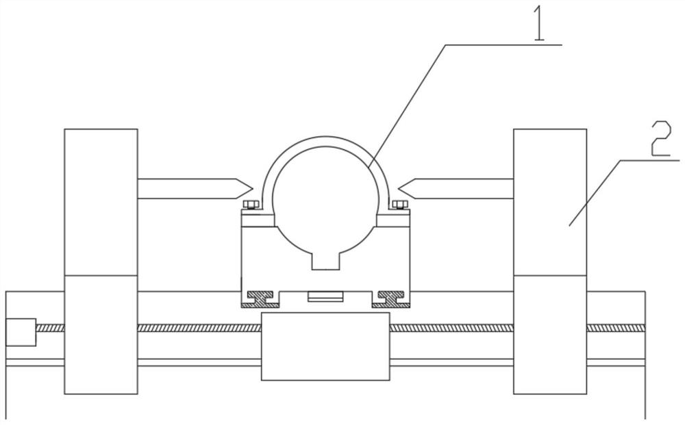
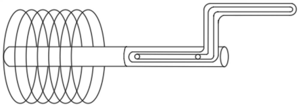
[0019] Embodiment 1: The front small catheter processing device is characterized in that the device includes a frame, a moving fixture 1, a grouting hole processing assembly 2 and a heating assembly 3, wherein:

[0020] An arc-shaped groove is arranged on the upper surface of the mobile fixture 1, the arc of the arc-shaped groove corresponds to the circumference of the small catheter, and a rectangular groove is arranged at the bottom of the arc-shaped groove, and the arc-shaped groove and the rectangular groove are connected; the mobile fixture 1 on the left and right sides of the arc-shaped groove is provided with hoops , the hoop is connected with the moving fixture 1 through bolts; the lower end surface of the moving fixture 1 is provided with a chute along the front and rear direction, and a slide rail matching the chute is fixed on the frame; the lower end surface of the moving fixture 1 is also provided with teeth along the front and rear direction. The rack is fixed wit...


PUM


Abstract

The invention relates to the technical field of advanced small guide pipe manufacturing, in particular to a machining device for an advanced small guide pipe for underground space, a hydraulic tunneland the like. The machining device comprises a machine frame, a movable clamp, a grouting hole machining assembly and a heating assembly. According to the machining device, the movable clamp slides along the machine frame, advances forwards and backwards in a gear transmission mode, advances stably and is reliable and durable, the contact area between the movable clamp and the advanced small guidepipe is large, the movable clamp and the advanced small guide pipe are tightly combined, and the pressure of a punching machine is conveniently borne; a left drilling machine and a right drilling machine are in linkage with each other and apply force to drill holes at the same time, so that the drilling efficiency is improved, in addition, the radial acting force of the small guide pipes is offset, and through the width design of fixing blocks, enough space is reserved between the drilling machines so as to avoid damage; and the heating assembly adopts a mode of heating inside and outside a steel pipe simultaneously, so that the heating efficiency is multiplied, and the machining device is worth of popularization.

Description

technical field [0001] The invention relates to the technical field of preparation of advanced small conduits, in particular to an advanced small conduit processing device for underground spaces and hydraulic tunnels. Background technique [0002] The advanced small conduit construction technology is a technological method in underground space and hydraulic tunnel engineering. It is mainly used for the weak broken zone, shallow buried section, tunnel entrance bias section, sand layer section, sand pebble section, and fault fracture during the self-stabilizing period. Pre-bracing on lighted lot. The advanced small conduit construction technology is a very effective auxiliary construction method for stabilizing the excavation face. In the construction of weak and broken rock formations, the advanced small conduit can reinforce the loose rock formation, and the loose and weak surrounding rock can be strengthened after grouting. The stability is conducive to the stability of th...

Claims


Application Information

Patent Timeline
IPC IPC(8): B23P23/04
CPCB23P23/04
Inventor 王晓方梁恩曹云祥尹齐军
Owner YUNNAN CONSTR & INSTALLATION JOINT STOCK
Learn More