
A device for preventing damage and perforation of protective clothing

A perforation device and damage technology, applied in textiles and papermaking, cutting of textile materials, metal processing, etc., can solve the problems of damage to the textile structure of protective clothing, difficult to control the accuracy of inner holes, and increased deformation of protective clothing. Convenience, lower production cost, lower tensile force effect

Active Publication Date: 2022-06-21
潍坊坤泽尔安全防护用品有限公司
View PDF0 Cites 0 Cited by
  • Summary
  • Abstract
  • Description
  • Claims
  • Application Information

AI Technical Summary

Problems solved by technology

[0003] The protective clothing is the same as the common clothing weaving method. They are all criss-crossed with silk threads. However, the silk threads of the protective clothing are denser and the tensile force between the threads is larger. Cutting and extrusion will cause further stretching and deformation of the silk thread. After cutting, the tensile force between the thread disappears, which will cause the thread around the perforation to relax, which will easily cause damage to the textile structure of the protective clothing. However, the extrusion cutting of the existing perforation equipment, Not only will it increase the deformation of the protective clothing, but at the same time it is difficult to control the precision of the inner hole after cutting. Different tools are required for different hole diameters, resulting in increased production costs.
[0004] For this reason, an anti-damage perforation device for protective clothing is provided to solve the production cost and perforation quality problems of knives

Method used


Image

  • A device for preventing damage and perforation of protective clothing
  • A device for preventing damage and perforation of protective clothing
  • A device for preventing damage and perforation of protective clothing

Examples


Embodiment Construction

[0025] The technical solutions in the embodiments of the present invention will be clearly and completely described below with reference to the accompanying drawings in the embodiments of the present invention. Obviously, the described embodiments are only a part of the embodiments of the present invention, but not all of the embodiments. Based on the embodiments of the present invention, all other embodiments obtained by those of ordinary skill in the art without creative efforts shall fall within the protection scope of the present invention.

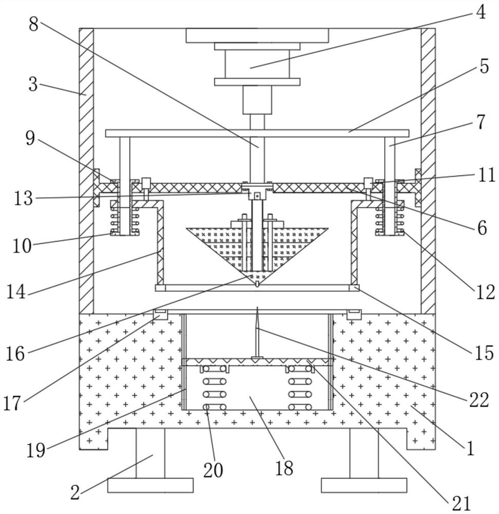
[0026] see Figure 1 to Figure 4 , the present invention provides a kind of technical scheme:

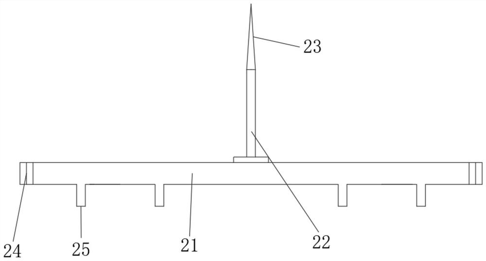
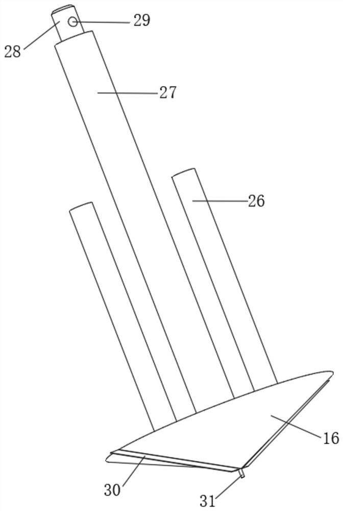
[0027] An anti-breakage perforation device for protective clothing, comprising a perforation processing table 1, the upper end surface of the perforation processing table 1 is vertically welded with side plates 3 symmetrically on the left and right sides, and the lower end surface of the perforation processing table 1 is provided with a pai...


PUM


Abstract

The invention relates to the technical field of protective clothing processing, in particular to an anti-damage perforating device for protective clothing, comprising a perforating processing table, a concave perforating inner cavity is opened downward in the middle of the upper end surface of the perforating processing table, and a bearing is arranged on the upper end of the perforating processing table. Pressure ring, the left and right sides of the upper end surface of the perforation processing table are symmetrically welded with side plates vertically, the beneficial effect is: the present invention realizes the extrusion of the textile thread around the perforation position of the protective clothing through the cooperation of the pressure ring and the pressure bearing ring Fixed, so as to reduce the stretching of the thread during the punching process, reduce the stretching force between the threads, reduce the degree of deformation of the thread after breaking, and greatly improve the quality of the perforation; by setting the positioning pin, the precise position of the perforation can be realized Positioning, at the same time, using the positioning pin on the protective clothing to realize the opening of the perforation position, which greatly facilitates the subsequent reaming and cutting, which not only improves the position accuracy of the perforation, but also increases the convenience of perforation cutting, reducing The squeeze force is reduced.

Description

technical field [0001] The invention relates to the technical field of protective clothing processing, in particular to an anti-breakage perforation device for protective clothing. Background technique [0002] The types of protective clothing include fire protective clothing, industrial protective clothing, medical protective clothing, military protective clothing and protective clothing for special groups. Protective clothing is mainly used in fire protection, military industry, shipbuilding, petroleum, chemical industry, painting, cleaning and disinfection, laboratory and other industries and departments. [0003] The protective clothing is the same as the common weaving method of clothing, which is made of criss-cross weaving with silk threads, while the silk threads of the protective clothing are more densely woven, and the tensile force between the threads is large. Cutting and extrusion will further stretch and deform the threads. After cutting, the tension between t...

Claims


Application Information

Patent Timeline
Patent Type & Authority Patents(China)
IPC IPC(8): B26F1/24B26D7/26B26D7/02B26D7/22B26D7/01D06H7/00
CPCB26F1/24B26D7/2614B26D7/2628B26D7/025B26D7/22B26D7/015D06H7/00B26F2210/16
Inventor 韩玲
Owner 潍坊坤泽尔安全防护用品有限公司
Learn More