Silk thread slitting and winding device for plastic woven bags

A technology of plastic woven bags and slitting rolls, which is applied in thin material handling, transportation and packaging, and delivery of filamentous materials, etc. It can solve the problems that the boom cannot move, affects the effect of roll materials, etc., and achieves the effect of simple structure

Inactive Publication Date: 2021-03-19
安徽聚屹新材料科技有限公司
View PDF0 Cites 2 Cited by
  • Summary
  • Abstract
  • Description
  • Claims
  • Application Information

AI Technical Summary

Problems solved by technology

[0004] What the present invention aims to overcome is that in the prior art, the distribution boom is fixed, so that the distribution boom cannot move with the increase of the diameter of the material roll, which affects the effect of the roll material. The purpose is to provide a plastic woven bag with silk cutting Winding device

Method used


Image

  • Silk thread slitting and winding device for plastic woven bags
  • Silk thread slitting and winding device for plastic woven bags
  • Silk thread slitting and winding device for plastic woven bags

Examples


Embodiment 1

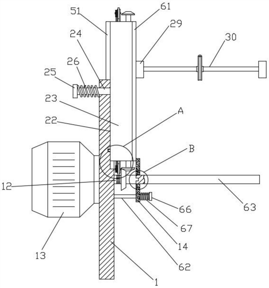
[0027] like Figure 1-2 Shown; A kind of silk thread cutting and winding device for plastic woven bags, comprising:

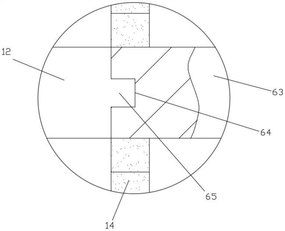
[0028] Coil material reel 1, the middle part of coil material reel 1 rotates and is installed with intermediate shaft 12, and one end of intermediate shaft 12 is connected with the output shaft of coil material motor 13, and the other end is connected with rewind seat 14, and coil material motor 13 is fixed on coil material reel 1;

[0029] The transmission bevel gear 21 is installed on the intermediate shaft 12, and the reel 1 is provided with an installation groove 22. The installation groove 22 is arranged along the radial direction of the intermediate shaft 12. A guide groove rail 23 is installed in the installation groove 22, and the middle part of the guide groove rail 23 is installed. There is a positioning shaft 24, the positioning shaft 24 is located in the middle of the guide groove rail 23, the positioning shaft 24 slides through the coil material re...

Embodiment 2

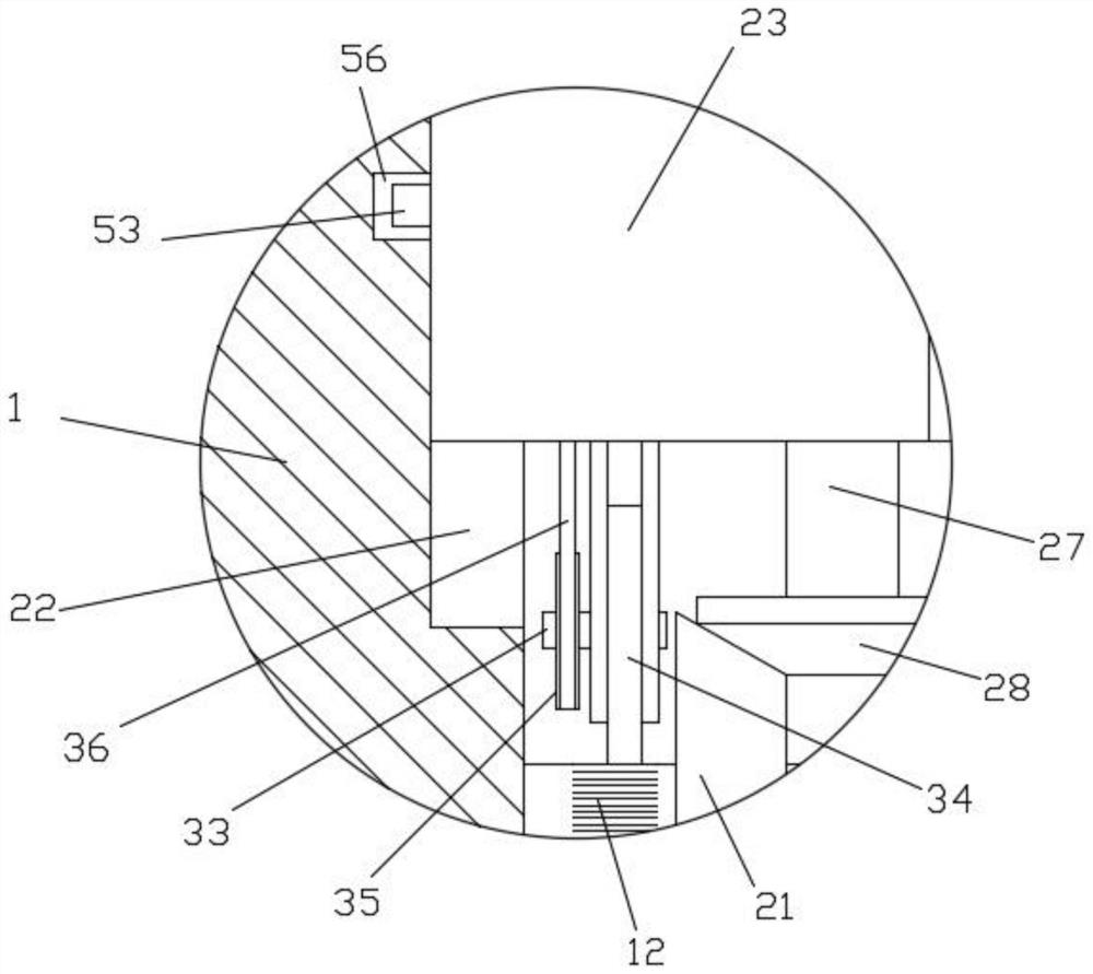
[0033] On the basis of Example 1, such as figure 2 , Figure 5 , Image 6 As shown; the cloth mechanism 30 includes a reciprocating screw rod 31 and a guide rod 32, the reciprocating screw rod 31 and the guide rod 32 are installed parallel to each other on the support base 29, and one end of the reciprocating screw rod 31 passes through the support base 29 and is inserted into the inside of the guide groove rail 23 , the two ends of the guide groove rail 23 are respectively equipped with a transmission shaft 33, and a friction wheel 34 is installed on the transmission shaft 33, and the friction wheel 34 at one end of the guide groove rail 23 contacts the intermediate shaft 12, and a belt pulley 35 is installed on the transmission shaft 33, and the belt pulley A toothed belt 36 is installed on the 35, a limit seat 37 is installed on the support seat 29, the toothed belt 36 passes through the limit seat 37, and the reciprocating screw mandrel 31 ends are fixed with a drive too...

Embodiment 3

[0038] On the basis of Example 2, such as figure 1 , figure 2 , Figure 7 As shown; when the support seat 29 moves to the end of the threaded rod 27, since the driven bevel gear 28 is still engaged on the transmission bevel gear 21, the threaded rod 27 still rotates, thus causing the support seat 29 to be stuck in the guide groove In the rail 23, in order to avoid the above-mentioned problems, a support plate 51 is provided on the side of the reel 1, the support plate 51 is arranged along the length direction of the installation groove 22, and the two ends of the guide groove rail 23 are respectively provided with through grooves 52, each through The inside of the groove 52 is independently equipped with a sliding rod 53, and the sliding rod 53 is located at the inner end of the guide groove rail 23 and is provided with a limit ring block 54. On the moving track of the seat 29, when the support seat 29 moves to the position of the sliding rod 53, the sliding rod 53 is squee...


PUM


Abstract

The invention relates to a silk thread slitting and winding device for plastic woven bags. The silk thread slitting and winding device for the plastic woven bags comprises a winding disc, wherein an intermediate shaft is rotatably installed in the middle of the winding disc; one end of the intermediate shaft is connected with an output shaft of a winding motor; the other end of the intermediate shaft is connected with a winding base; the winding motor is fixed onto the winding disc; the intermediate shaft is driven to rotate by the winding motor; a transmission bevel gear on the intermediate shaft is meshed with a driven bevel gear to drive a threaded rod in a guide grooved rail to rotate; the threaded rod pushes a supporting seat to move in the guide grooved rail; the supporting seat slowly moves away from the intermediate shaft along with increase of the diameter of a material roll, so that a cloth mechanism on the supporting seat is effectively prevented from making contact with thematerial roll; and after winding is completed, a pressing base can be extruded to enable the guide grooved rail to be moved out of a mounting groove, at the moment, the guide grooved rail can be rotated, the driven bevel gear is replaced to make contact with the transmission bevel gear, and the supporting seat on the turned guide grooved rail gets close to the material roll, so that second-roundwinding operation is facilitated.

Description

technical field [0001] The invention relates to the field of manufacturing plastic woven bags, in particular to a silk cutting and winding device for plastic woven bags. Background technique [0002] Plastic woven bag, also known as snakeskin bag. It is a kind of plastic bag, used for packaging, and its raw materials are generally various chemical plastic raw materials such as PP and PE. There are 6 billion woven bags used for cement packaging in my country every year, accounting for more than 85% of the bulk cement packaging. In addition to being used for cement packaging, plastic woven container bags are widely used in industrial and agricultural product packaging, aquatic product packaging, and poultry feed packaging; therefore, the market demand for plastic woven bags is still very large. , by wire-drawing the plastic, and then using the wire-drawn plastic rope to weave into a tube, by cutting the tube-shaped braided material, and then sewing the edge after cutting, th...

Claims


Application Information

Patent Timeline
Patent Type & Authority Applications(China)
IPC IPC(8): B65H54/28B65H54/74
CPCB65H54/2818B65H54/74B65H2403/43
Inventor 李芳刘娟王耀明
Owner 安徽聚屹新材料科技有限公司
Why Eureka
Try Eureka