
A pressure swing adsorption nitrogen generator with high production efficiency

A pressure swing adsorption and production efficiency technology, applied in mixers, inorganic chemistry, nitrogen compounds, etc., can solve the problems of reduced production efficiency of nitrogen generators, increased risk of deflagration, oxygen enrichment, etc., to simplify maintenance difficulty, The effect of high production efficiency and easy replacement

Active Publication Date: 2022-05-20
SUZHOU EVERYWHERE GAS EQUIP
View PDF0 Cites 0 Cited by
  • Summary
  • Abstract
  • Description
  • Claims
  • Application Information

AI Technical Summary

Problems solved by technology

[0003] The purpose of the present invention is to provide a pressure swing adsorption nitrogen generator with high production efficiency to solve the problem that the existing nitrogen generator proposed in the above background technology is usually not equipped with a dilution device, and it is easy to cause the exhaust gas to be directly discharged into the air. Oxygen is enriched near the equipment, which increases the risk of deflagration, and the adsorbent of the existing nitrogen generator is usually located in the same adsorption tank as the gas to be separated, and when the nitrogen in the adsorption tank is discharged, it will inevitably cause pressure In order to avoid oxygen desorption and mixing into nitrogen due to low air pressure, it is necessary to retain a part of nitrogen to maintain air pressure, and this part of nitrogen is discharged together with desorbed oxygen, which reduces the production efficiency of the nitrogen generator

Method used


Image

  • A pressure swing adsorption nitrogen generator with high production efficiency
  • A pressure swing adsorption nitrogen generator with high production efficiency
  • A pressure swing adsorption nitrogen generator with high production efficiency

Examples


Embodiment Construction

[0029] The following will be combined with the accompanying drawings in the embodiments of the present invention, the technical solution in the embodiments of the present invention will be described clearly and completely, it is clear that the embodiments described are only a part of the embodiment of the present invention, not all embodiments. Based on embodiments in the present invention, all other embodiments obtained by those of ordinary skill in the art without making creative work, are within the scope of protection of the present invention.

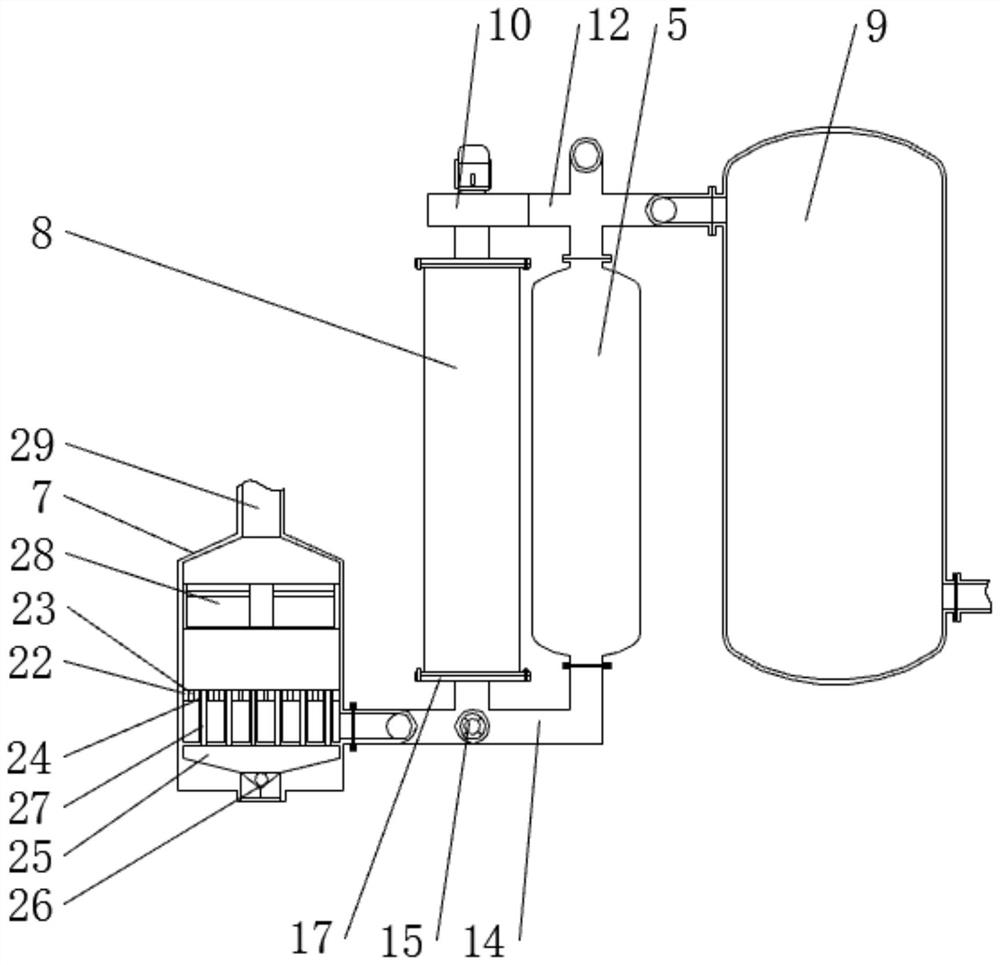
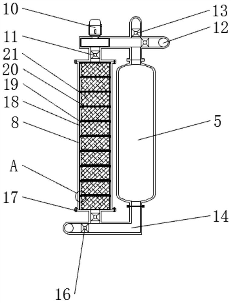
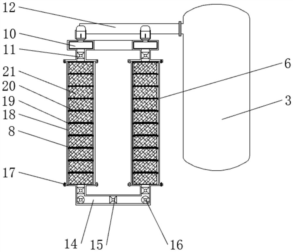
[0030] See Figure 1-7 , the present invention provides a technical solution: a highly productive pressure swing adsorption nitrogen making machine, such as Figure 1 and Figure 4 As shown, the air compressor 1 left connection is provided with an air purification device 2, and the air purification device 2 left connection is provided with an air storage tank 3, the air storage tank 3 is provided with a first transfer tank 4 and a second t...


PUM


Abstract

The invention discloses a pressure swing adsorption nitrogen generator with high production efficiency, which comprises an air compressor, a centrifugal fan, an end cover and a partition plate. An air purification device is connected to the left side of the air compressor, and the air purification device An air storage tank is connected to the left side, and a first transfer gas tank and a second transfer gas tank are arranged behind the air storage tank, and the first transfer gas tank is arranged in front of the second transfer gas tank. The pressure swing adsorption nitrogen generator with high production efficiency is equipped with a gas mixing tank and an exhaust fan. The desorbed oxygen enters the gas mixing tank through the second connecting pipe, and the oxygen enters the upper side of the gas mixing tank through the vent hole, while The exhaust fan extracts the air from the lower side of the mixing tank to move upward, so that the outside air enters the air cavity under the action of negative pressure, and the air in the air cavity enters the upper side of the mixing tank through the air guide tube, so that the oxygen and the air are evenly mixed , which greatly reduces the concentration of oxygen, reduces the probability of deflagration accidents, and is safer to use.

Description

Technical field [0001] The present invention relates to the field of nitrogen making machine technology, specifically a highly productive pressure swing adsorption nitrogen making machine. Background [0002] Nitrogen is widely used in medical surgery, electronic product manufacturing and fertilizer manufacturing and other industries, so it is necessary to use the nitrogen machine, of which the pressure swing adsorption nitrogen machine has the advantages of simple process flow and high degree of automation, the nitrogen machine produces a higher proportion of oxygen in the exhaust gas, but the existing nitrogen machine is usually not provided with a dilution device, directly the exhaust gas is discharged in the air easily leads to oxygen enrichment near the equipment, and then increases the risk of deflagration, which has certain safety risks when used. And the adsorbent of the existing nitrogen making machine is usually located in the same adsorption tank as the gas to be separ...

Claims


Application Information

Patent Timeline
Patent Type & Authority Patents(China)
IPC IPC(8): C01B21/04B01D53/047B01D53/26B01F23/10B01F25/00B01F35/71
CPCC01B21/045B01D53/047B01D53/26C01B2210/0014B01F23/10B01F25/00B01F35/712
Inventor 吴天月葛来香
Owner SUZHOU EVERYWHERE GAS EQUIP
Learn More