Aero-engine turbine rim sealing structure

A technology of aero-engine and turbine, applied in the direction of engine components, machines/engines, mechanical equipment, etc., can solve the problems of complex rim sealing and so on

Active Publication Date: 2021-03-19
AECC COMML AIRCRAFT ENGINE CO LTD
View PDF7 Cites 3 Cited by
  • Summary
  • Abstract
  • Description
  • Claims
  • Application Information

AI Technical Summary

Problems solved by technology

[0008] The technical problem to be solved by the present invention is to provide an aero-engine turbine rim seali

Method used


Image

  • Aero-engine turbine rim sealing structure
  • Aero-engine turbine rim sealing structure
  • Aero-engine turbine rim sealing structure

Examples


Embodiment Construction

[0047] In order to make the above objects, features and advantages of the present invention more comprehensible, specific implementations of the present invention will be described in detail below in conjunction with the accompanying drawings.

[0048] Embodiments of the present invention will now be described in detail with reference to the accompanying drawings. Reference will now be made in detail to the preferred embodiments of the invention, examples of which are illustrated in the accompanying drawings. Wherever possible, the same numbers will be used throughout the drawings to refer to the same or like parts.

[0049] In addition, although the terms used in the present invention are selected from well-known and commonly used terms, some terms mentioned in the description of the present invention may be selected by the applicant according to his or her judgment, and the detailed meanings thereof are set forth herein described in the relevant section of the description. ...


PUM


Abstract

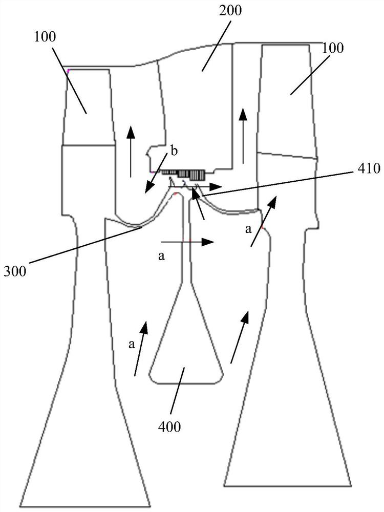
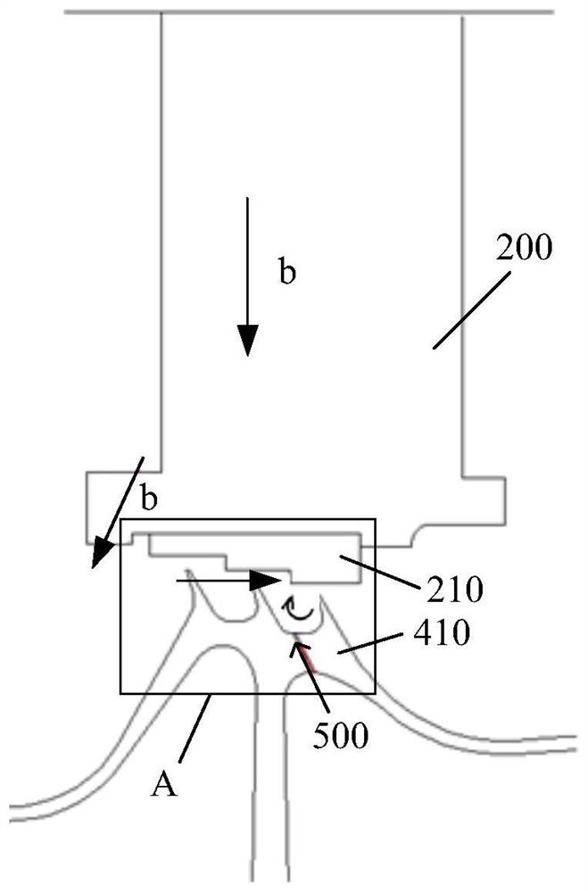
The invention provides an aero-engine turbine rim sealing structure. The aero-engine turbine rim sealing structure comprises multiple stages of rotor blades, multiple stages of stator blades, multiplestages of rotating discs and interstage sealing discs, the multiple stages of rotor blades and the corresponding multiple stages of rotating discs are vertically connected in a one-to-one correspondence mode, and the rotor blades and the stator blades are arranged at intervals. The interstage sealing discs are arranged between every two adjacent rotating discs. A labyrinth structure is arranged at the top of each interstage sealing disc and located below the corresponding stator blades, at least one first vent hole is formed between tooth parts of the labyrinth structure, part of cooling gasflows into a cavity between the tooth parts through the first vent holes. The mixed gas flows into a rear edge wheel sealing cavity of each stator blade after being mixed with sealing gas. According to the aero-engine turbine rim sealing structure, a small flow path is added to exhaust air between tooth parts of the labyrinth structure, so that radial impact jet flow is formed while the back pressure of backward flowing of front sealing airflow is improved, and the flowing of axial backward airflow of tooth tips is hindered.

Description

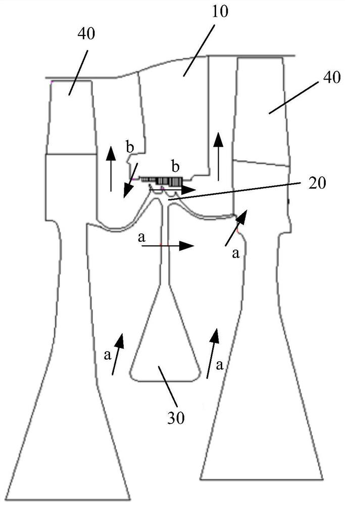
technical field [0001] The invention relates to the field of aero-engine air systems, in particular to an aero-engine turbine rim sealing structure. Background technique [0002] In the prior art, in the design process of the air system of an aeroengine, cooling of high-temperature components, rotor axial force balance, sealing of bearings, and sealing of rims between rotors and stators must be met under the requirement of a certain amount of bleed air. Among them, the main purpose of sealing the rim is to prevent the high-temperature gas from the main channel from flowing into the engine disc cavity, which will cause problems such as excessive temperature of the disc cavity, over-temperature of the disc shaft, and excessive strength. [0003] figure 1 It is a schematic diagram of the sealing flow path of the front and rear flanges of the traditional guide vane. Such as figure 1 As shown, after the sealing gas b passes through the second-stage stator blade 10 of the high-...

Claims


Application Information

Patent Timeline
IPC IPC(8): F01D11/08
CPCF01D11/08
Inventor 孙平平王代军邓双国
Owner AECC COMML AIRCRAFT ENGINE CO LTD
Why Eureka
Try Eureka