
Microbial fertilizer production system

A microbial fertilizer and production system technology, applied in the field of microbial fertilizer production system, can solve the problems of high labor intensity, complex design structure, and low production efficiency, and achieve the effect of meeting continuous production requirements, high degree of automation, and improving production efficiency

Pending Publication Date: 2021-03-19
辽宁盛德源微生物科技有限责任公司
View PDF3 Cites 0 Cited by
  • Summary
  • Abstract
  • Description
  • Claims
  • Application Information

AI Technical Summary

Problems solved by technology

[0002] Microbial fertilizers mainly use the life activities of certain microorganisms to enable crops to obtain specific fertilizer effects. In addition to containing a large number of beneficial microorganisms, microbial fertilizers also contain many other elements. General microbial fertilizers include inorganic substances, phosphorus, potassium, organic matter, and medium Elements, microbial bacteria, trace elements and other components. During the production of microbial fertilizers, the above-mentioned component materials are first formulated into raw materials according to specific proportions, and then the raw materials are stirred and mixed thoroughly, and then formed by granulation, drying, cooling and other procedures. Granular fertilizers, but in the prior art, the preparation of microbial fertilizer raw materials is mainly done manually, the labor intensity of workers is high and the production efficiency is low
[0003] Secondly, in the production process of microbial fertilizers, the semi-finished products formed after the raw materials are stirred and granulated need to enter the dryer for drying, and then be cooled. In the above process, dust floating objects will be generated. The dust is usually directly discharged after being treated by dust removal equipment, but in actual production, it is found that these dust floats contain a large amount of organic fertilizer and other floats, and these organic fertilizer floats are smaller in particle size and lighter in weight than other dusts , it is possible to recycle it
In addition, the cooling equipment in the prior art mainly adopts the combination of water cooling and air cooling, and its design structure is relatively complicated, the cost is high, and it is difficult to meet the requirements of mass continuous production
[0004] Furthermore, for microbial fertilizers, due to the high humidity of the semi-finished products, it is very easy to adhere to the inner wall of the dryer cylinder, causing problems such as material blockage, so it is necessary to equip the drying cylinder with a vibration device to make the material be separated by vibration. Cylinder wall, the current common vibration structure method is to install vibrating rods at equal intervals on the outer wall of the drying cylinder. It was found that due to the large volume and long length of the drying cylinder, and the vibrating rod head can only realize vibration stripping in a limited area around, the stripping effect needs to be improved. Therefore, in order to solve the above problems, there have been many Other forms of vibrating device structures, such as the above-mentioned patent with the authorized announcement number CN211012214U, which set a plurality of vibration motors outside the cylinder to achieve vibration stripping, but this method has a high cost, and another example is the Chinese patent with the authorized announcement number CN209524740U. The invention patent discloses a vibrating device for a composite microbial fertilizer dryer, which is provided with a number of hollow elbow covers on the wall of the dryer cylinder, and vibrating balls are arranged in the hollow elbow covers to adhere to the inner wall of the outer cylinder. The semi-finished material on the vibrator is separated by vibration, but this method is the same as the vibrating rod, which can only affect the vibration and separation of the material in the surrounding limited area.

Method used


Image

  • Microbial fertilizer production system
  • Microbial fertilizer production system
  • Microbial fertilizer production system

Examples


Embodiment Construction

[0041] The present invention will be described in further detail below in conjunction with the accompanying drawings.

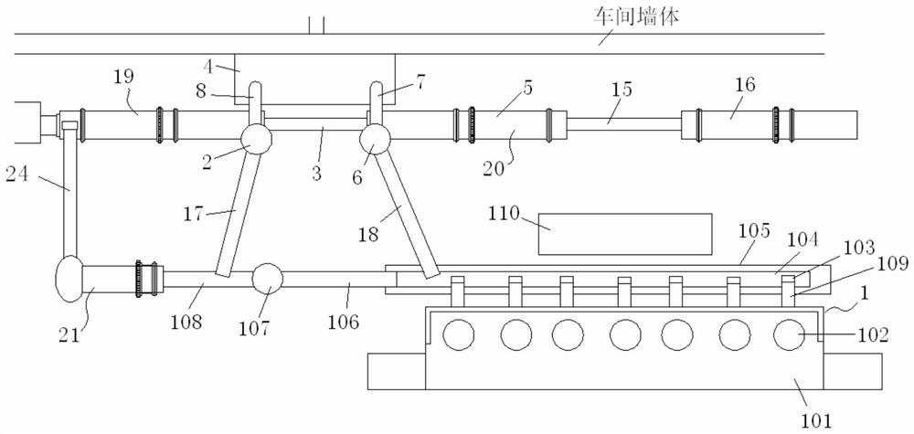
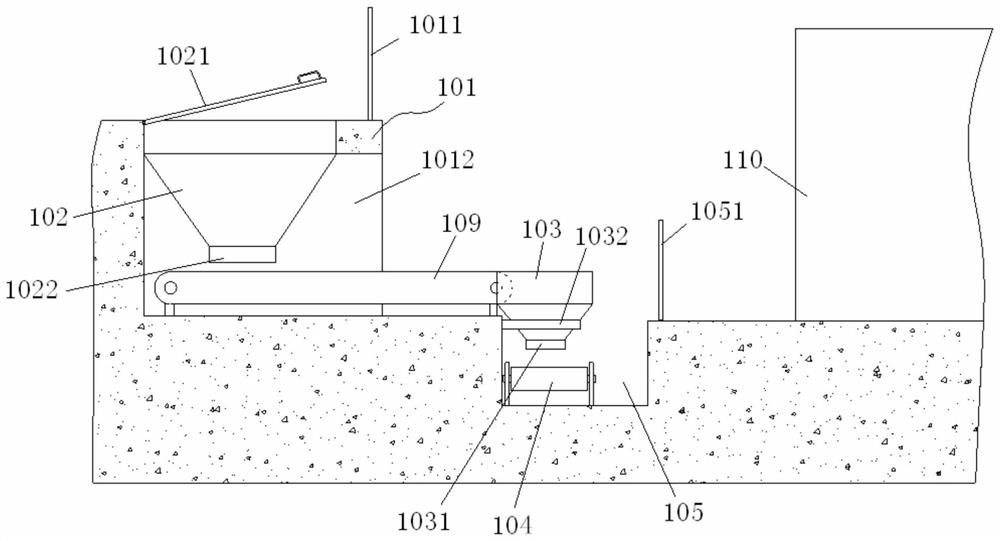
[0042] Such as Figure 1-16 As shown, the present invention comprises a raw material batching system 1, a granulator 21, a drying device 19, a cooling system 20, an ash storage room 4, a first recycling conveyor belt 17 and a second recycling conveyor belt 18, wherein the raw material batching system 1 is set A discharge conveyor belt 108 is connected to the granulator 21, the granulator 21 is connected to the input end of the drying device 19 through a granulation output conveyor belt 24, and the cooling system 20 includes the first cooling cylinder 5, the middle The conveyor belt 15 and the second cooling cylinder 16, and the output end of the drying device 19 is connected to the input end of the first cooling cylinder 5 through a drying output conveyor belt 3, as Figure 11 As shown, one side of the output end of the drying device 19 is connected to the a...


PUM


Abstract

The invention relates to the field of microbial fertilizer production, in particular to a microbial fertilizer production system, a raw material batching system is provided with a discharge conveyingbelt connected with a granulator, the granulator, a drying device and a first cooling cylinder in a cooling system are sequentially connected through different conveying belts; one side of an output end of the drying device is communicated with an ash storage chamber; the other side of the output end is provided with a first air inducing hopper ; the upper side of the ash storage chamber is connected with the first air inducing hopper through a first circulating pipeline; an input end of a first recycling conveying belt is arranged below the first air inducing hopper, an output end of the first recycling conveying belt is arranged above a discharging conveying belt; one side of an input end of the first cooling cylinder is communicated with the ash storage chamber, and the other side of the input end of the first cooling cylinder is provided with the second air inducing hopper; and the upper side of the ash storage chamber is connected with the second air inducing hopper through a second circulating pipeline, an input end of a second recycling conveying belt is arranged below the second air inducing hopper, and an output end is arranged in the raw material batching system. The microbial fertilizer production system provided by the invention can realize automatic batching and recycling of fertilizer floaters, and ensures sufficient dust removal.

Description

technical field [0001] The invention relates to the field of microbial fertilizers, in particular to a microbial fertilizer production system. Background technique [0002] Microbial fertilizers mainly use the life activities of certain microorganisms to enable crops to obtain specific fertilizer effects. In addition to containing a large number of beneficial microorganisms, microbial fertilizers also contain many other elements. General microbial fertilizers include inorganic substances, phosphorus, potassium, organic matter, and medium Elements, microbial bacteria, trace elements and other components. During the production of microbial fertilizers, the above-mentioned component materials are first formulated into raw materials according to specific proportions, and then the raw materials are stirred and mixed thoroughly, and then formed by granulation, drying, cooling and other procedures. Granular fertilizers, but in the prior art, the preparation of microbial fertilizer ...

Claims


Application Information

Patent Timeline
Patent Type & Authority Applications(China)
IPC IPC(8): F25D17/06F25D31/00F26B11/04F26B21/00F26B25/00F26B25/04F26B25/12F26B25/16F28C3/18F28F5/02
CPCF25D17/06F25D31/00F26B11/0477F26B21/001F26B25/002F26B25/04F26B25/12F26B25/16F28C3/18F28F5/02
Inventor 金福艳李新
Owner 辽宁盛德源微生物科技有限责任公司
Learn More