


Quick Research
Generate reliable direction feasibility study reports for your R&D in just a few steps.

Technical Q&A
Discover and master advanced knowledge NOW. Basics, ideas, possibilities, all at once.

Find Solutions
As an expert in R&D theories, this can generate solutions to your technical problems instantly.

Evaluate Feasibility
Analyze your overall solution with one click, know your potential R&D risks in advance.

Monitor Landscape
Get weekly tech updates, stay abreast of the latest tech innovations and key insights.
Digital holographic three-dimensional topography measurement device and method
A three-dimensional topography and digital holography technology, applied in measurement devices, optical devices, instruments, etc., can solve problems such as the inability to achieve fast real-time topography measurement, achieve fast real-time topography measurement, reduce measurement time, avoid The effect of the phase unwrapping process
- Summary
- Abstract
- Description
- Claims
- Application Information
AI Technical Summary
Problems solved by technology
Method used
Image


Examples
Embodiment 1
[0074] An embodiment of the present invention provides a digital holographic three-dimensional shape measurement device. The digital holographic three-dimensional shape measurement device in this embodiment includes: a laser, a light splitting component, an object light path for irradiating an object to be measured, and a reference light for reference Optical path, optical path synthesis component, acquisition system including multiple sensors;
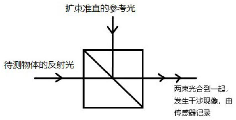
[0075] The light splitting component divides the light emitted by the laser into two beams, the first beam of light irradiates the object to be measured through the object light path, and the object to be measured reflects the first beam of light irradiated; the second beam of light is used as a reference light It is transmitted by the reference light optical path, and the reference light transmitted by the reference light optical path and the reflected light of the object to be measured are combined in the optical path synthesis compo...
Embodiment 2
[0087] An embodiment of the present invention also provides a measurement method based on the above-mentioned digital holographic three-dimensional shape measurement device, the method may include the following steps:
[0088] S1. Adjust the detection surface of the sensor in the acquisition system, and record the angle information of the adjusted detection surface of each sensor relative to the central sensor.
[0089] In this embodiment, the angle information of the detection surface of each sensor can be adjusted through the aforementioned electronically controlled rotating platform and translation platform.
[0090] The angular information may be angular information relative to the central sensor axis.
[0091] S2. Start the laser, and acquire holographic information of the reference light and the reflected light that interfere.
[0092] Calibration is performed by computing equipment such as a computer to control the movement and rotation of the translation platform and ...
Embodiment 3
[0144] An embodiment of the present invention also provides a method for processing a hologram, which may include the following steps:
[0145] A1. The computing device acquires the holographic information of the reference light and the reflected light that interfere.
[0146] In this embodiment, the holographic information includes phase information detected by multiple sensors, and the multiple sensors have a certain rotation angle with respect to the central sensor among them, and furthermore, there is an oblique phase factor in the phase information.
[0147] A2. Reconstruct the holographic information to obtain a three-dimensional shape of the object to be measured.
[0148] Specifically, it may include:
[0149] A21. Reconstruct the holographic information based on the conjugate light of the reference light collected in the collection system, and obtain the object light field information in the form of complex amplitude for extracting phase information,
[0150] A22. B...
PUM
 Abstract
Description
Claims
Application Information
 - R&D Engineer
- R&D Manager
- IP Professional
- Industry Leading Data Capabilities
- Powerful AI technology
- Patent DNA Extraction
Browse by: Latest US Patents, China's latest patents, Technical Efficacy Thesaurus, Application Domain, Technology Topic, Popular Technical Reports.
© 2024 PatSnap. All rights reserved.Legal|Privacy policy|Modern Slavery Act Transparency Statement|Sitemap|About US| Contact US: help@patsnap.com