
A cross laser emitting device that can automatically adjust in the roadway

An automatic adjustment and cross laser technology, which is applied to active optical measuring devices, measuring devices, tunnels, etc., can solve the problems of short laser receiving distance, single monitoring parameters, and no automatic adjustment, so as to improve tunneling efficiency and collection Effect of distance, reducing adjustment time

Active Publication Date: 2022-05-31
LIAONING TECHNICAL UNIVERSITY
View PDF5 Cites 0 Cited by
  • Summary
  • Abstract
  • Description
  • Claims
  • Application Information

AI Technical Summary

Problems solved by technology

However, due to the influence of geological conditions and equipment vibration, it is more difficult to monitor the position and orientation parameters of the excavation equipment in real time, resulting in the inability of the excavation equipment to excavate and walk according to the set route, and unable to achieve rapid excavation
In addition, the current laser emitting device in the roadway emits in the form of a laser beam, and the monitoring parameters are single, so it is impossible to monitor the multi-pose parameters of the excavation equipment, and the receiving distance of the laser is short, and there is no automatic adjustment function, which increases the reliability of the laser emitting device. The number of station shifts and manual adjustment time affect the tunneling efficiency

Method used


Image

  • A cross laser emitting device that can automatically adjust in the roadway
  • A cross laser emitting device that can automatically adjust in the roadway
  • A cross laser emitting device that can automatically adjust in the roadway

Examples


Embodiment Construction

[0089] The present invention will be further described below in conjunction with the embodiments of the present invention, and the technical solutions in the embodiments of the present invention will be further described.

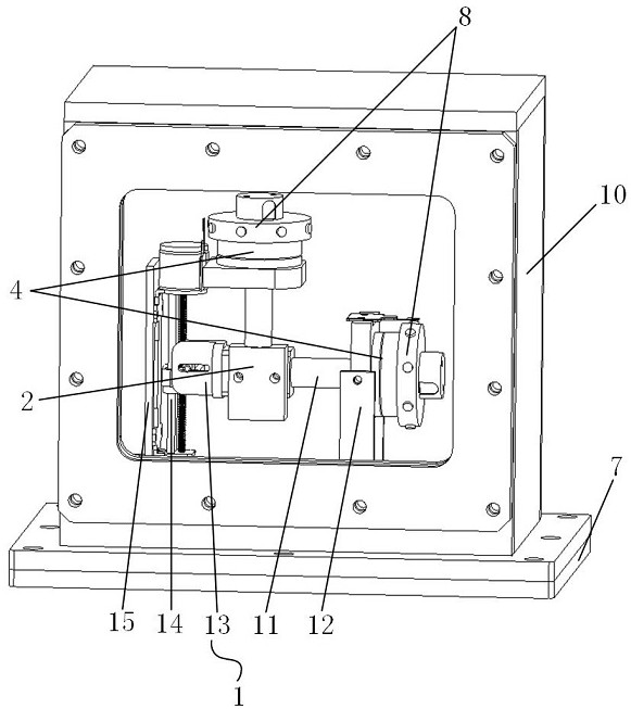
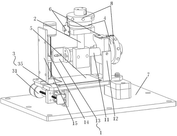
[0091] The present embodiment provides a cross laser emitting device that can be automatically adjusted in a roadway, and the structure is shown in FIG. 1 .

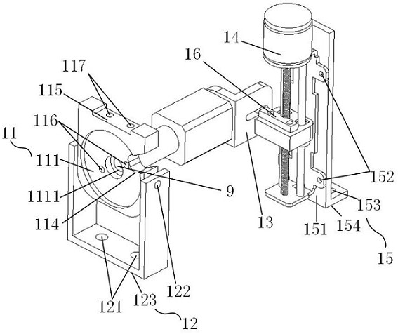
[0094] As shown in FIG. 3 and FIG. 4, the vertical laser pen holder 11 includes a first concave platform 111, a first convex platform 112, a first side concave

[0096] As shown in FIG. 6, the laser pointer end cap 13 includes an end cap recess 131, an end cap assembly hole 132 and a vertical motor guide

[0097] As shown in FIG. 3, the vertical motor base 15 is L-shaped and includes a first side surface 151, a first motor assembly threaded hole 152,

[0098] As shown in FIG. 7 , the first sliding shaft 16 includes a sliding shaft mounting hole 161 , a guide rail groove 162 and a sliding shaft rod 163 .

...


PUM


Abstract

The invention provides a cross laser emission device that can be automatically adjusted in the roadway, including a vertical emission adjustment device, a horizontal laser pen holder, a horizontal adjustment device, a rotating motor, an emission circuit board, a detection circuit board, a base, a laser reflection group, two Laser emitter head, housing, multiple gaskets, and flexible electrical connections. The invention adopts a rotating motor to drive the rotation of the triangular prism, converts two laser beams into scanning beams to form a cross laser, and realizes real-time monitoring of multi-pose parameters of the tunneling equipment in the roadway. The emitting circuit board of the laser emitting device contains an inclination detection module, which can automatically adjust the laser emitting device, reduces the manual adjustment time of the laser emitting device, and improves the efficiency of rapid tunneling. The various devices and components are connected by flexible electrical connectors, which can adapt to fluctuations in the process of moving the laser emitting device and self-adjustment process, and facilitate assembly.

Description

A cross laser emitting device that can be automatically adjusted in a roadway technical field The present invention relates to roadway excavation navigation system measurement equipment field, particularly relate to a kind of roadway that can automatically adjust ten word laser transmitter. Background technique With the development of roadway excavation automation and intelligence, in the rapid excavation system, in order to realize the system of the excavation equipment [0002] In order to implement systematic walking and intelligent cutting control, real-time monitoring of its pose parameters must be completed. However, due to geological conditions and equipment vibration The influence of the movement increases the difficulty of real-time monitoring of the pose parameters of the excavation equipment, resulting in the inability of the excavation equipment to follow the set route. Excavation and walking cannot achieve rapid excavation. In addition, the current laser...

Claims


Application Information

Patent Timeline
Patent Type & Authority Patents(China)
IPC IPC(8): G01C15/00E21D9/00
CPCG01C15/004G01C15/008E21D9/003
Inventor 杨辛未王鑫李鹏飞陈洪月田立勇陈洪岩李云成杨威张帅
Owner LIAONING TECHNICAL UNIVERSITY
Learn More