Design of an active detection module for combating optical covert observation

A technology of active detection and main control module, which is applied in the fields of public security, anti-terrorism and security, armed police, and national defense. The effect of sensitivity

Active Publication Date: 2022-05-27
ARMY ENG UNIV OF PLA
View PDF7 Cites 0 Cited by
  • Summary
  • Abstract
  • Description
  • Claims
  • Application Information

AI Technical Summary

Problems solved by technology

[0004] The existing active detection method adopts laser active illumination, and utilizes the "cat's eye effect" of the optical lens assembly of the optical observation equipment to cause strong reflection signals different from surrounding targets, combined with the optical focal plane array imaging component to realize the rapid detection of hidden targets. This method has two main disadvantages: First, the active detection laser must be within the working wavelength range of the lens of the optical covert observation equipment, and the incident angle must be within the field of view of the optical lens, such as long-wave infrared observation, while short-wave infrared The "cat's-eye effect" cannot be produced when the laser in the wavelength band irradiates it. If the incident angle of the laser deviates from the field of view of the optical lens, the "cat's-eye effect" will not be produced; the second is the combination of laser illumination and focal plane array imaging detector. The active detection laser has relatively strong power, the far-field energy distribution density of the light field is relatively uniform, and the imaging detector has high sensitivity, and there are also some restrictions on the working distance

Method used


Image

  • Design of an active detection module for combating optical covert observation
  • Design of an active detection module for combating optical covert observation

Examples


Embodiment Construction

[0023] In order to facilitate the understanding and implementation of the present invention by those of ordinary skill in the art, the present invention will be further described in detail below with reference to the embodiments. It should be understood that the embodiments described herein are only used to illustrate and explain the present invention, but not to limit the present invention.

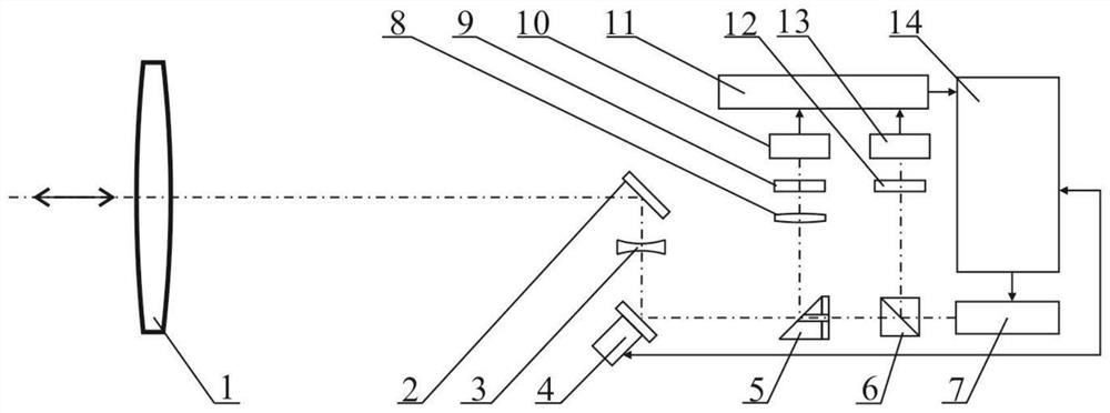
[0024] like figure 1 As shown, an active detection module design for counteracting optical concealment observation includes a convex lens 1, a reflecting mirror 2, a concave lens 3, a two-dimensional fast mirror assembly 4, a hole-digging mirror 5, a beam splitter 6, a laser 7, a focusing mirror Optical lens 8 , narrow-band filter 9 , first photoelectric avalanche tube 10 , detection amplifier circuit 11 , attenuator 12 , second photoelectric avalanche tube 13 , and main control module 14 .

[0025] The laser 7 adopts a 1.5Xum eye-safe band laser. After the radiation beam is split by the...


PUM


Abstract

The invention discloses an active detection module for resisting optical covert observation, which includes a convex lens, a reflector, a concave lens, a two-dimensional fast mirror assembly, a hole-digging mirror, a beam splitter, a laser, a condenser lens, and a narrow-band filter 1. The first photoelectric avalanche tube, the detection amplifier circuit, the attenuation sheet, the second photoelectric avalanche tube and the main control module. According to the maximum light intensity of laser emission and the maximum light intensity of laser echo, the present invention calculates the target distance value and reflectivity, and can realize the rough detection of reflectivity of optical lens of different materials such as visible light, mid-infrared, and far-infrared, and adopts similar reflectance distribution The area and the corresponding similar reflectivity, combined with the optical lens type-lens reflectivity-optical lens area table, can realize the preliminary judgment of the type of optical concealed observation equipment; solve the problem that it is difficult to detect concealed optical observation equipment in the day and night environment; High sensitivity, wide applicable wavelength range and low power consumption.

Description

technical field [0001] The invention relates to the design of an active detection module for countering optical concealment observation in the fields of national defense, public security, armed police, anti-terrorism and security protection, and can realize active detection of concealed optical observation equipment in day and night environments. Background technique [0002] The development of optoelectronic technology has promoted the rapid development of optoelectronic passive observation equipment, and promoted the wide application of passive observation equipment based on visible light imaging, low-light night vision imaging, and mid-to-far infrared imaging in national defense, security, and other fields. Then, due to its passive observation characteristics, finding such targets becomes a difficult point in the adversarial field. [0003] Optical covert observation generally considers the common observation methods of the detector, such as visible light CCD or infrared ...

Claims


Application Information

Patent Timeline
Patent Type & Authority Patents(China)
IPC IPC(8): G01M11/02
CPCG01M11/02G01M11/0207
Inventor 黎伟程勇万强韦尚方米朝伟曹海源初华刘旭刘云田方涛
Owner ARMY ENG UNIV OF PLA
Why Eureka
Try Eureka