Device and method for testing performance of magnetohydrodynamic inertia momentum wheel

A magnetohydrodynamics and inertial momentum technology, which is applied in the direction of measuring devices, measuring electricity, and measuring electrical variables, etc., can solve the problems of fluid flow state influence, angular momentum and output torque magnitude are small, and cannot meet the measurement accuracy requirements, etc. Achieving good feasibility and high precision

Pending Publication Date: 2021-03-19
THE FRONTIER TECH RES INST OF TIANJIN UNIV
View PDF3 Cites 1 Cited by
  • Summary
  • Abstract
  • Description
  • Claims
  • Application Information

AI Technical Summary

Problems solved by technology

[0003] Different from the traditional momentum wheel, the magnetohydrodynamic inertial momentum wheel uses the rotating flow of conductive fluid to output torque and angular momentum. Its theoretical research and performance index test need to obtain the fluid flow velocity of the momentum wheel under a certain input current, and the fluid is located in the closed In the torus channel, its rotational speed is difficult to measure directly; at the same time, the fluid flow state is easily affected by the internal shape of the pipeline, and gener...

Method used


Image

  • Device and method for testing performance of magnetohydrodynamic inertia momentum wheel
  • Device and method for testing performance of magnetohydrodynamic inertia momentum wheel

Examples


Embodiment Construction

[0019] The present invention will be described in further detail below in conjunction with the accompanying drawings and specific embodiments. It should be understood that the specific embodiments described here are only used to explain the present invention, not to limit the present invention.

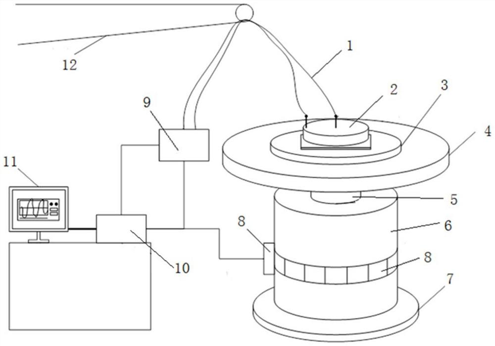
[0020] The experimental device for testing the performance of the magnetohydrodynamic inertial momentum wheel of this embodiment, its structure is as attached figure 1 As shown, the composition mainly includes: fixed tooling 3 , photoelectric code disc 8 , power amplification drive circuit 9 , data acquisition card 10 , and upper computer 11 . The single-axis air-floating turntable is composed of the load mounting plate 4, the air-floating shaft 5, the main body of the air-floating turntable 6 and the base 7 of the air-floating turntable, and is equipped with a photoelectric code disc 8 for speed measurement, and the magnetohydrodynamic inertial momentum wheel 2 passes through The fi...


PUM


Abstract

The invention discloses a device and a method for testing the performance of a magnetohydrodynamic inertia momentum wheel, and the method comprises the steps: enabling the magnetohydrodynamic inertiamomentum wheel which is pre-machined and assembled to be installed on an air-floating turntable with a photoelectric encoder, giving a test control signal through a data collection card through an upper computer, under the excitation of a power amplification drive circuit, synchronously collecting the input driving current of the magnetohydrodynamic inertia momentum wheel and the rotating speed ofthe air floatation turntable, and calculating to obtain the average flow velocity, the output torque and the angular momentum of the conductive fluid according to the rotating speed of the air floatation turntable, the rotating inertia of the air floatation turntable, the rotating inertia of a conductive fluid ring and the input driving current and a formula provided based on the angular momentumconservation principle and the working principle of the magnetohydrodynamic inertia momentum wheel. According to the invention, the actuating principle of the magnetohydrodynamic inertia momentum wheel can be indirectly verified, the output torque and angular momentum performance characteristics of the magnetohydrodynamic inertia momentum wheel are tested, and the blank in the field of magnetohydrodynamic inertia momentum wheel test experiment research is filled.

Description

technical field [0001] The invention belongs to the field of performance testing of new inertial devices, and in particular relates to a device and method for testing the performance of a magnetohydrodynamic inertial momentum wheel. Background technique [0002] The magnetohydrodynamic inertial momentum wheel is a new type of momentum wheel, its actuation characteristics are based on the magnetohydrodynamic effect, the core component is a conductive fluid ring, and the conductive fluid is placed in a closed torus channel. In the orthogonal magnetic field, it is driven by the Lorentz force to rotate and flow, and the torque output and angular momentum are realized through the interaction between the conductive fluid and the magnetic field. It can be used as the actuator in the micro-satellite attitude control system to realize the control and Stablize. [0003] Different from the traditional momentum wheel, the magnetohydrodynamic inertial momentum wheel uses the rotating fl...

Claims


Application Information

Patent Timeline
IPC IPC(8): G01M13/00G01R31/00
CPCG01M13/00G01R31/00
Inventor 李醒飞闫冬杰钟莹
Owner THE FRONTIER TECH RES INST OF TIANJIN UNIV
Why Eureka
Try Eureka