Rock micro-defect three-dimensional reconstruction method and system

A three-dimensional reconstruction, micro-defect technology, applied in the direction of optical testing flaws/defects, measuring devices, instruments, etc., to achieve the effect of ensuring integrity

Pending Publication Date: 2021-03-19
HEFEI UNIV OF TECH
View PDF8 Cites 0 Cited by
  • Summary
  • Abstract
  • Description
  • Claims
  • Application Information

AI Technical Summary

Problems solved by technology

[0005] In view of the deficiencies in the above-mentioned technologies, the present invention provides a method and system for three-dimensional reconstruction of rock micro-defects, which are used to solve the problem that surface micro-defects are easily overlooked and the edge accuracy is poor when simple CT scanning me

Method used


Image

  • Rock micro-defect three-dimensional reconstruction method and system
  • Rock micro-defect three-dimensional reconstruction method and system
  • Rock micro-defect three-dimensional reconstruction method and system

Examples


Embodiment 1

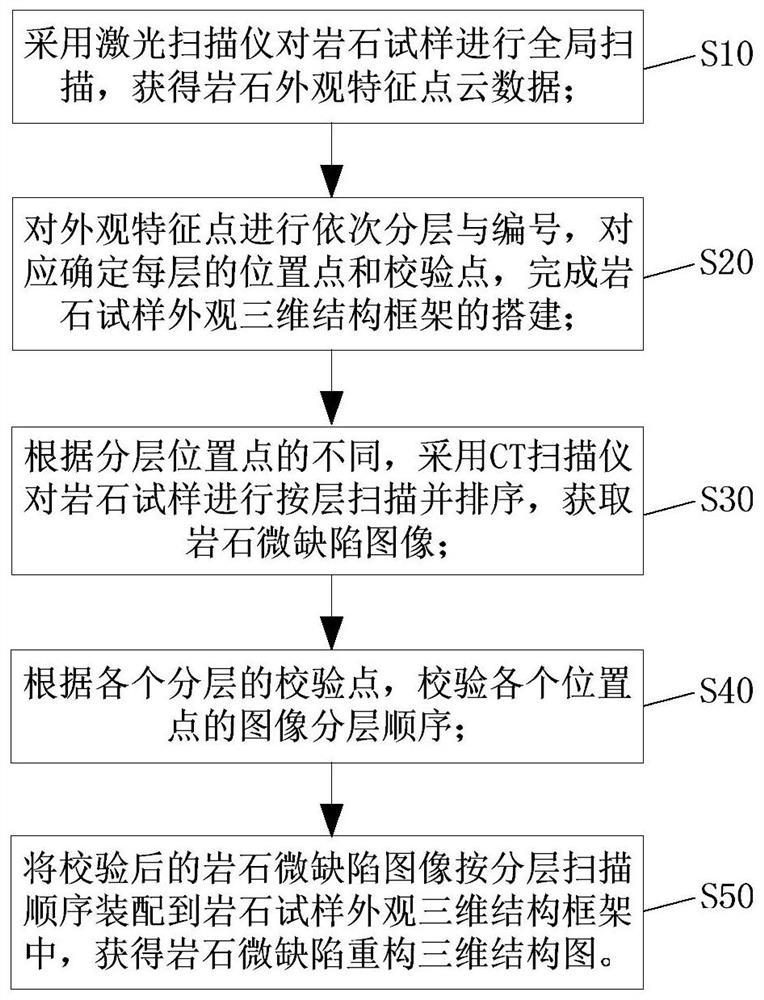
[0073] Such as figure 1 As shown, the method for three-dimensional reconstruction of rock micro-defects provided by the embodiment of the present invention includes the following steps:

[0074] S10, using a laser scanner to globally scan the rock sample to obtain rock appearance characteristic point cloud data;

[0075] S20, sequentially layering and numbering the appearance feature points, correspondingly determining the position points and verification points of each layer, and completing the construction of the three-dimensional structural framework of the appearance of the rock sample;

[0076] S30, using a CT scanner to scan and sort the rock samples layer by layer according to different layer positions, to obtain images of rock micro-defects;

[0077] S40, according to the check point of each layer, check the image layering sequence of each position point;

[0078] S50 , assembling the checked rock micro-defect images into the three-dimensional structure framework of ...

Embodiment 2

[0083] On the basis of Example 1, the embodiment of the present invention also provides an implementation method for improving the accuracy of data acquisition, that is, before using a laser scanner to perform a global scan on the rock sample, such as Figure 5 shown, also includes the steps:

[0084] S60, evenly distributing spherical targets around the rock sample.

[0085] Specifically, at least 3 pairs of staggered targets are set between adjacent stations that collect data: on the one hand, it is necessary to ensure that there are no less than 3 pairs of targets between every two adjacent stations that collect data, so as to ensure that the experimental The accuracy of the data collected during the process; on the other hand, the spherical targets on the rock samples should be staggered as much as possible to avoid placing them on the same straight line, so as to facilitate the registration of adjacent data points with the same name in the later stage.

[0086] In order ...

Embodiment 3

[0090] On the basis of Embodiment 1, the embodiment of the present invention provides an implementation manner in which the sharpness of the image outline does not meet the requirements and affects the accuracy of the three-dimensional reconstruction. Specifically, in step S30, after using a CT scanner to scan and sort by layer, as Figure 7 shown, also includes the steps:

[0091] S31, performing binarization processing on the scanned and sorted rock micro-defect image data;

[0092] S32, check one by one whether the binarized images of each layered position point meet the requirements of three-dimensional reconstruction for image contour clarity: if not, bring the layer number corresponding to the layered position point into the CT scanner to specify the position Secondary scanning to obtain and replace images that meet the contour definition requirements;

[0093] S33. Correspondingly update the position point and check point of the replaced image, and verify the image la...


PUM


Abstract

The invention discloses a rock micro-defect three-dimensional reconstruction method. The method comprises the following steps: performing global scanning on a rock sample by adopting a laser scanner to obtain rock appearance feature point cloud data; sequentially layering and numbering the appearance feature points, correspondingly determining a position point and a check point of each layer, andcompleting the construction of a rock sample appearance three-dimensional structure frame; according to different position points, using a CT scanner to scan and sort the rock samples layer by layer,and acquiring rock micro-defect images; verifying the image layering sequence of each position point according to the verification point of each layer; and assembling the verified rock micro-defect images into a rock sample appearance three-dimensional structure frame according to a layered scanning sequence to obtain a rock micro-defect reconstruction three-dimensional structure diagram. The method solves problems that surface micro-defects are easy to ignore and the edge precision is insufficient when rock micro-defect three-dimensional reconstruction is carried out by pure CT scanning, andthe invention provides a laser and CT scanning combined rock micro-defect three-dimensional accurate reconstruction method and system.

Description

technical field [0001] The present invention relates to the technical field of three-dimensional reconstruction of rock micro-defects, more specifically, the present invention relates to a method and system for three-dimensional reconstruction of rock micro-defects based on CT scanning and laser scanning technologies. Background technique [0002] A series of projects such as coal mines, tunnels, underground water conservancy structures and nuclear waste storage are closely related to the promotion of the national economy and the improvement of national defense strength. As such projects continue to be built deep in the formation, they have a higher impact on the stability of deep rock masses requirements. There are pores, fissures, joints, faults and other multi-scale discontinuous structures in the underground rock mass. The physical and mechanical properties of the rock are always directly or indirectly affected by the pores, joints, and fissures in the rock. Physical an...

Claims


Application Information

Patent Timeline
IPC IPC(8): G01N23/046G01B11/24G01N21/95
CPCG01N23/046G01B11/24G01N21/95
Inventor 王志亮李松玉贾帅龙
Owner HEFEI UNIV OF TECH
Why Eureka
Try Eureka