Electric power cabinet convenient to internal device maintenance

A technology of power cabinets and devices, which is applied in the direction of electrical components, substation/power distribution device shells, substation/switch layout details, etc., can solve problems such as difficulty in extending arms, large safety hazards, inconvenient operation, etc., to reduce difficulty and facilitate The effect of maintenance and improvement of maintenance efficiency

Inactive Publication Date: 2021-03-19
丁亮
View PDF10 Cites 1 Cited by
  • Summary
  • Abstract
  • Description
  • Claims
  • Application Information

AI Technical Summary

Problems solved by technology

[0003] The power control cabinet is to assemble the switchgear, measuring instrument, protective device and auxiliary equipment in the closed or semiclosed metal cabinet or on the screen width according to the requirements of electrical wiring. The safety of people and surrounding equipment. When the existing power control cabinet is in use, various electrical equipment are installed inside the control cabinet. When it is necessary to overhaul the components inside the control cabinet, workers need to extend their arms into the control cabinet for maintenance. , the interior of the control cabinet is often dark and covered by the cabinet, making it difficult for maintenance workers to stretch their arms, and the operation of the maintenance process is inconvenient. At the same time, the electrical equipment in the existing power control cabinet will generate a lot of heat when it works for a long time , if the heat dissipation is not performed in time, the equipment will often be damaged due to high temperature, and the safety hazard is relatively large. Therefore, this utility provides a power control cabinet that is convenient for internal device maintenance to solve the above problems

Method used


Image

  • Electric power cabinet convenient to internal device maintenance
  • Electric power cabinet convenient to internal device maintenance
  • Electric power cabinet convenient to internal device maintenance

Examples


Embodiment Construction

[0028] The following will clearly and completely describe the technical solutions in the embodiments of the present invention with reference to the accompanying drawings in the embodiments of the present invention. Obviously, the described embodiments are only some, not all, embodiments of the present invention.

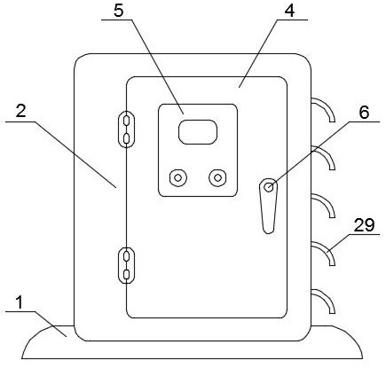
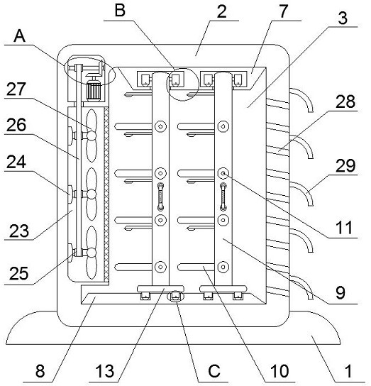
[0029] refer to Figure 1-5 , a power cabinet for easy maintenance of internal components, including a waterproof base 1, a power cabinet main body 2 is arranged on the waterproof base 1, a cabinet door 4 is connected to the power cabinet main body 2 through hinge rotation, and a cabinet door 4 is fixedly installed on the cabinet door 4. The control panel 5 and the cabinet door 4 are provided with a door bolt 6. The use of the power cabinet can be monitored in real time through the control panel 5. The cabinet door 4 is closed to realize the sealing state of the main body 2 of the power cabinet. Open the cabinet door 4 to perform maintenance and operation. Simple, at...


PUM


Abstract

The invention discloses a power cabinet convenient to internal device maintenance. The power cabinet comprises a waterproof pedestal, the waterproof pedestal is provided with a power cabinet main body, the power cabinet main body is internally provided with a control groove, and the inner top wall of the control groove is fixedly provided with a top plate. By pulling a handle, a first roller rollsin a moving groove, a second roller rolls in a sliding groove, and a equipment mounting plate is pulled out of the control groove through cooperation of the first roller and the second roller, so that workers are prevented from being shielded by the power cabinet main body when maintaining electrical equipment; The invention solves the problem that when an existing power cabinet is used, a workerneeds to stretch an arm into a control groove for maintenance, great convenience is brought to maintenance of the worker, flowing air generated by rotation of a fan enters the control groove throughan air net, the air flowing speed in the control groove is increased, and a large amount of heat generated when the electrical equipment works for a long time is discharged from the heat dissipation opening, so that heat dissipation of the control groove is realized, and the situation that the electrical equipment is damaged due to high temperature caused by untimely heat dissipation is effectively avoided.

Description

technical field [0001] The invention relates to the technical field of power cabinets, in particular to a power cabinet that facilitates maintenance of internal devices. Background technique [0002] The electrical appliances in life are constantly increasing, and a lot of manual labor is replaced by electronic equipment. The stability of power needs to be guaranteed by qualified equipment. The power control cabinet is a common power control device, which is convenient for stable and safe transmission of power. The electricity needed by people for daily life is convenient for life, study and work. [0003] The power control cabinet is to assemble the switchgear, measuring instrument, protective device and auxiliary equipment in the closed or semiclosed metal cabinet or on the screen width according to the requirements of electrical wiring. The safety of people and surrounding equipment. When the existing power control cabinet is in use, various electrical equipment are inst...

Claims


Application Information

Patent Timeline
Patent Type & Authority Applications(China)
IPC IPC(8): H02B1/56H02B1/32H02B1/28
CPCH02B1/565H02B1/32H02B1/28
Inventor 丁亮
Owner 丁亮
Why Eureka
Try Eureka