A dc-dc power supply compensation control circuit based on voltage-controlled delay line

A DC-DC, voltage-controlled delay technology, applied in control/regulation systems, electrical components, regulating electrical variables, etc., can solve problems affecting transient response, PWM controller failure, high power, etc., to achieve wide voltage output range, the effect of eliminating inherent delays

Active Publication Date: 2022-05-27
ZHEJIANG UNIV
View PDF4 Cites 0 Cited by
  • Summary
  • Abstract
  • Description
  • Claims
  • Application Information

AI Technical Summary

Problems solved by technology

[0005] At this stage, there are several problems in the design of high-frequency DC-DC converters: first, when the switching period is reduced to tens of nanoseconds or less, it may cause the PWM controller based on the slope comparator to fail, and additional measures are required to meet high-frequency requirements; secondly, larger comparator delays limit the duty cycle range, which not only affects transient response, but also limits the input / output operating voltage range
Reducing ripple requires high-precision ADC and DPWM, both of which consume a lot of power and increase the complexity of the design
[0006] The traditional solution uses a sawtooth wave and a control voltage to generate a drive signal by comparing it with a comparator, such as figure 1 As shown, when the output signal is disturbed, the feedback signal of the traditional scheme generates a control signal through the path of the compensator module and compares it with the reference signal to obtain a PWM signal. Due to the inherent delay of the comparator, the voltage conversion at a very high switching frequency range will be severely limited

Method used


Image

  • A dc-dc power supply compensation control circuit based on voltage-controlled delay line
  • A dc-dc power supply compensation control circuit based on voltage-controlled delay line
  • A dc-dc power supply compensation control circuit based on voltage-controlled delay line

Examples


Embodiment Construction

[0028] In order to describe the present invention more specifically, the technical solutions of the present invention will be described in detail below with reference to the accompanying drawings and specific embodiments.

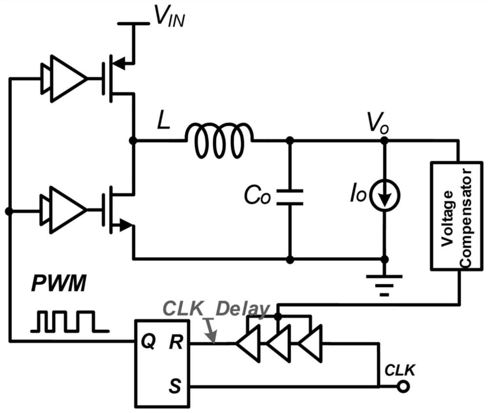
[0029] The present invention is based on the DC-DC power supply compensation scheme of the voltage-controlled delay line. The system includes a DC-DC power supply topology circuit, a driving circuit, a compensator, a voltage-controlled delay line and a logic control circuit, such as figure 2 As shown, the output voltage of the power stage of the DC-DC converter generates a feedback voltage through the voltage divider network, and the feedback voltage outputs the control voltage through the compensation network, which is used as the control signal of the voltage-controlled delay line, the external clock and the voltage-controlled delay line. The output terminals of the RS flip-flop are respectively connected to the S terminal and the R terminal of the RS fli...


PUM


Abstract

The invention discloses a DC-DC power supply compensation control circuit based on a voltage-controlled delay line, which is divided into two parts: a compensation circuit and a delay line. The voltage-controlled output point is connected to the control terminal of the delay line, and the voltage-controlled output point is a feedback voltage. After the output position of the compensation circuit, the external interface of the delay line includes an external clock signal input terminal, a delay signal output terminal, and a control terminal. The input terminal of the delay line is connected to the clock signal, and the voltage control is converted to Time control function. At the same time, the present invention uses the traditional Type III circuit compensation network as the voltage control part to output the control voltage to control the delay of the delay line to ensure that the phase difference between the output of the delay line and the external clock meets the control requirements, that is, the duty cycle meets the current The state requirements make it possible to realize a wide output voltage range without affecting the stability; compared with the traditional control mode, the present invention has the advantages of simple circuit structure, high efficiency, fast transient response and the like.

Description

technical field [0001] The invention belongs to the technical field of integrated circuit design, and specifically designs a DC-DC power supply compensation control circuit based on a voltage-controlled delay line. Background technique [0002] DC / DC converters are voltage converters that effectively output a fixed voltage after converting the input voltage. DC / DC converters are divided into three categories: step-up DC / DC converters, step-down DC / DC converters and buck-boost converters type DC / DC converter. Three types of control can be used according to the needs. The PWM control type has high efficiency and good output voltage ripple and noise; the PFM control type has the characteristics of low power consumption under small loads; the PWM / PFM conversion type implements PFM control when the load is small. And automatically switch to PWM control under heavy load. [0003] DC-DC converters are ubiquitous in power supply equipment, they are used to generate supply voltage ...

Claims


Application Information

Patent Timeline
Patent Type & Authority Patents(China)
IPC IPC(8): H02M3/158H02M1/088
CPCH02M3/158H02M1/088
Inventor 郭吉放屈万园杨旭曹海啸
Owner ZHEJIANG UNIV
Why Eureka
Try Eureka