
Tool for modifying a support surface

A technology for supporting surfaces and tools, which is applied in the photoengraving process, grinding tools, photoengraving process exposure devices and other directions of the pattern surface, and can solve problems such as unevenness

Pending Publication Date: 2021-03-19
ASML NETHERLANDS BV
View PDF2 Cites 0 Cited by
  • Summary
  • Abstract
  • Description
  • Claims
  • Application Information

AI Technical Summary

Problems solved by technology

However, it has been found that when the substrate table WT and substrate holder (and any other elements) are assembled or mounted, unevenness can also result

Method used


Image

  • Tool for modifying a support surface
  • Tool for modifying a support surface
  • Tool for modifying a support surface

Examples


Embodiment Construction

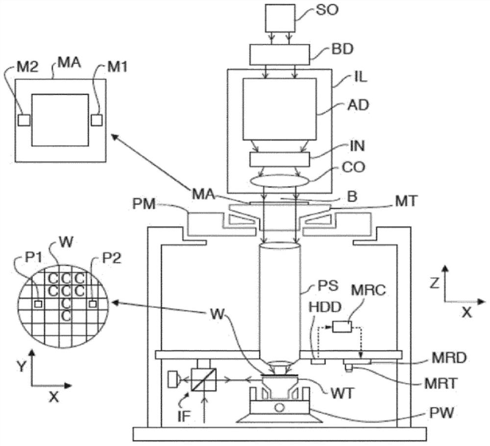
[0029] figure 1 A lithographic apparatus according to an embodiment of the invention is schematically depicted. The apparatus comprises: an illumination system (illuminator) IL configured to condition a radiation beam B (e.g. ultraviolet radiation or any other suitable radiation); a patterning device support or support structure (e.g. a mask table) MT configured to support The patterning device (eg mask) MA is also connected to a first positioning device PM configured to accurately position the patterning device according to certain parameters. The lithographic apparatus also includes a substrate table (e.g. wafer table) WT or "substrate support" configured to hold a substrate (e.g. a resist-coated wafer) W and connected to a second positioner PW , the second positioner is configured to accurately position the substrate according to certain parameters. The substrate support may comprise a substrate table WT (otherwise referred to as a chuck) on which a substrate holder is su...


PUM

PropertyMeasurementUnit
Diameteraaaaaaaaaa

Abstract

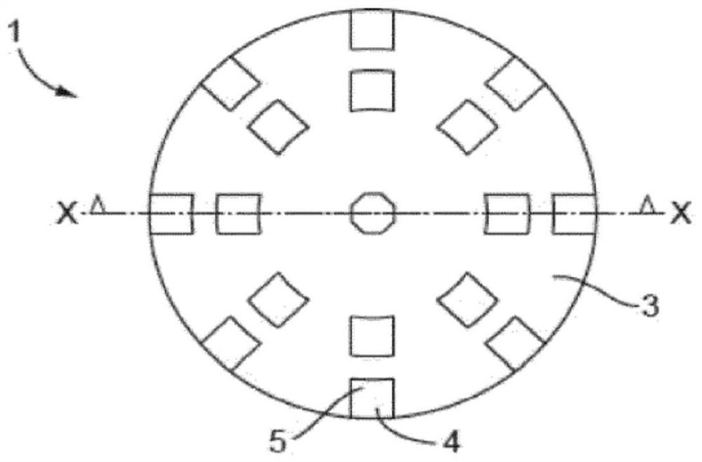
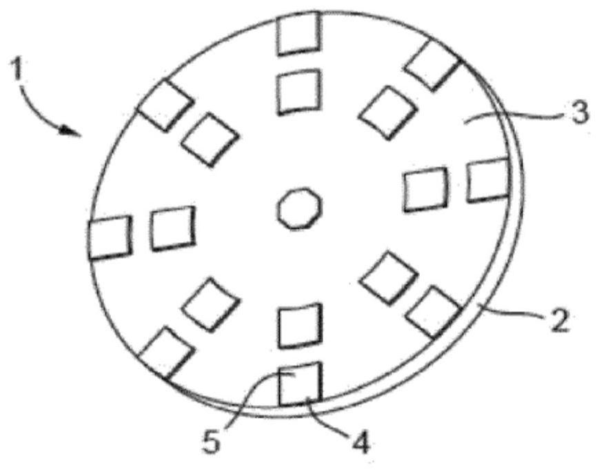
A tool (1) for modifying substrate support elements (21) of a substrate holder (20), the substrate support elements having support surfaces (22) for supporting a substrate, said tool comprising a mainbody (2) having a main body surface (3), wherein the tool comprises multiple protrusions (4) from the main body surface, the multiple protrusions having distal ends (5) configured to contact the support surfaces and to modify the substrate support elements. Furthermore, a lithographic apparatus and a method comprising such a tool are disclosed.

Description

technical field [0001] This application claims priority from European Application 18185938.0, filed on 27 July 2018 and the entire content of which is hereby incorporated by reference. technical field [0002] The invention relates to a tool for modifying a holder, a method for modifying a holder using the tool and a lithographic apparatus comprising the tool. Background technique [0003] A lithographic apparatus is a machine that applies a desired pattern to a substrate, usually to a target portion of the substrate. For example, lithographic equipment may be used in the manufacture of integrated circuits (ICs). In this case, a patterning device (alternatively referred to as a mask or reticle) may be used to generate the circuit patterns to be formed on the various layers of the IC. The pattern can be transferred onto a target portion (eg, a portion comprising one or more dies) on a substrate (eg, a silicon wafer). The transfer of the pattern is usually via imaging ont...

Claims


Application Information

Patent Timeline
IPC IPC(8): G03F7/20B24B37/14B24B37/12B24B37/16H01L21/687
CPCB24B37/14B24B37/16G03F7/707G03F7/70925H01L21/6875G03F7/7085
Inventor B·D·肖尔滕P·A·M·比勒肯斯关天男T·林德伊杰H·A·梅哈格诺尔J·M·W·范德温克尔C·J·P·M·范努南H·T·J·F·范弗塞维尔德M·M·P·A·韦尔默朗
Owner ASML NETHERLANDS BV
Learn More