
Magnetic particle grinding machine and method suitable for surfaces of crankshafts and non-standard shaft entities

A technology for grinding machines and crankshafts, which is applied to machine tools, grinding machines, and grinding drive devices designed for grinding the rotating surface of workpieces. Avoid processing limitations, simple operation, and high grinding precision

Active Publication Date: 2021-03-23
UNIV OF SCI & TECH LIAONING
View PDF13 Cites 0 Cited by
  • Summary
  • Abstract
  • Description
  • Claims
  • Application Information

AI Technical Summary

Problems solved by technology

When the special grinding machine processes crankshafts and non-standard shafts, the effective processing area of ​​the grinding wheel and the abrasive belt is limited, and the corresponding shaft surface can only be processed in two dimensions; the special grinding machine has the disadvantages of complex structure, cumbersome operation, and expensive equipment.

Method used


Image

  • Magnetic particle grinding machine and method suitable for surfaces of crankshafts and non-standard shaft entities
  • Magnetic particle grinding machine and method suitable for surfaces of crankshafts and non-standard shaft entities
  • Magnetic particle grinding machine and method suitable for surfaces of crankshafts and non-standard shaft entities

Examples


Embodiment Construction

[0035] The specific embodiment of the present invention will be further described below, but it is not used to limit the scope of the present invention:

[0036] Example:

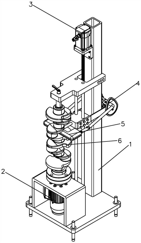
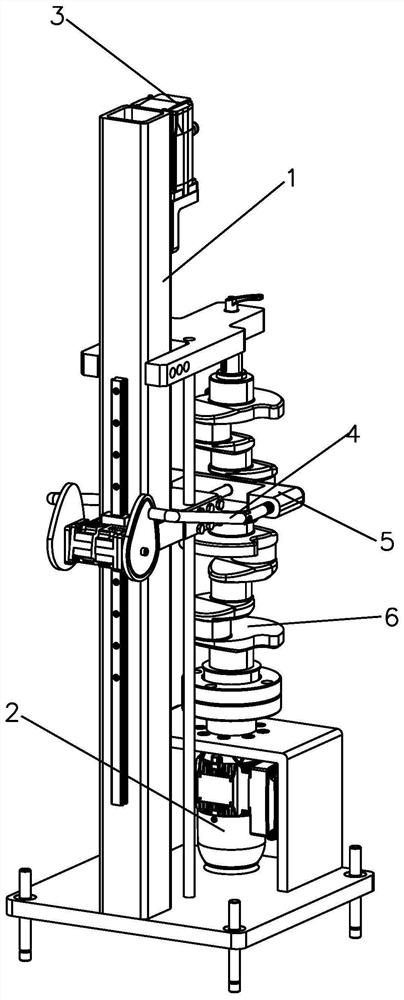
[0037] Such as figure 1 , figure 2 As shown, the magnetic particle grinding machine suitable for crankshaft and non-standard shaft solid surface includes frame 1 and drive device 2 installed on frame 1, lifting device 3, magnetic particle grinding follower device 4 and magnetic brush 5 .

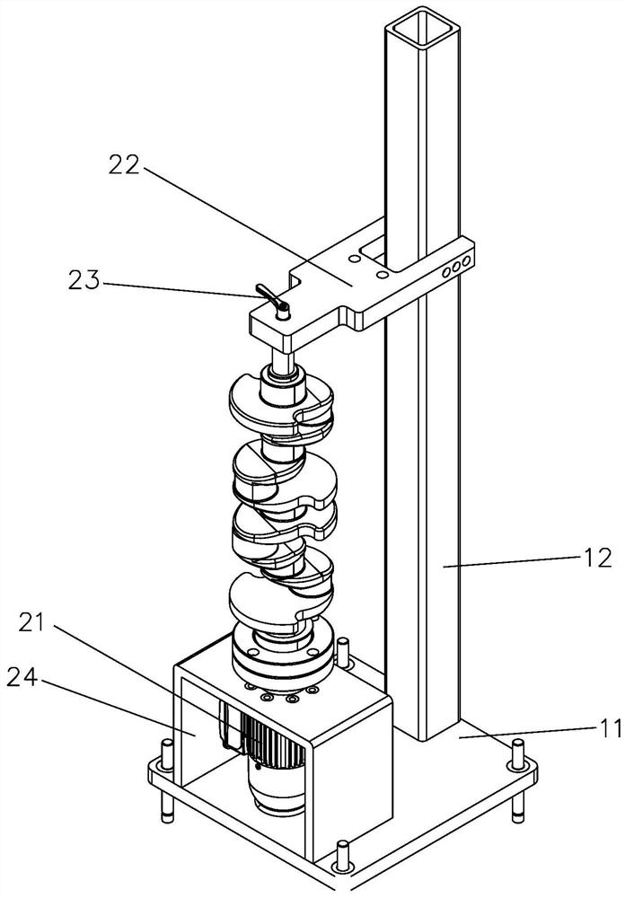
[0038] Such as Figure 1-4 As shown, the frame 1 includes a bottom platform 11, a column 12 and a slide rail 13; the bottom platform 11 is a platform parallel to the horizontal plane, the column 12 is vertically fixed on the bottom platform 11, and the slide rail 13 is vertically fixed on the column 12. The slide rail 13 is perpendicular to the bottom platform 11.

[0039] Such as image 3 As shown, the driving device 2 includes a driving motor 21 , an upper end support 22 , a manual tightening wrench 23 and a driv...


PUM


Abstract

The invention relates to the technical field of magnetic particle grinding, in particular to a magnetic particle grinding machine and method suitable for the surfaces of crankshafts and non-standard shaft entities. The magnetic particle grinding machine comprise a machine frame, a driving device, a lifting device, a magnetic particle grinding follow-up device and a magnetic brush, wherein the machine frame, the driving device, the lifting device, the magnetic particle grinding follow-up device and the magnetic brush are installed on the machine frame; the driving device is connected with a crankshaft or a non-standard shaft and drives the crankshaft or the non-standard shaft to do rotation motion; the lifting device is connected with the magnetic particle grinding follow-up device and drives the magnetic particle grinding follow-up device to reciprocate along the axis of the crankshaft or the non-standard shaft; the magnetic particle grinding follow-up device is connected with the magnetic brush, and the magnetic particle grinding follow-up device enables the magnetic brush to follow the surface of the crankshaft or the non-standard shaft to be ground and to be kept at the machining distance of 2-3 mm all the time, so that the surface of the crankshaft or the non-standard shaft to be ground is ground; and the quality and uniformity of the surface of the crankshaft can be guaranteed, the to-be-machined surface can be machined conveniently, the cost is low, and the grinding effect is good.

Description

technical field [0001] The invention relates to the technical field of magnetic particle grinding, in particular to a magnetic particle grinding machine and method suitable for solid surfaces of crankshafts and non-standard shafts. Background technique [0002] Ultra-precision machining technology is one of the important symbols to measure the level of science and technology of a country, and has become the most important part of the machinery manufacturing industry. As one of the most important parts in the engine, the precision of the crankshaft directly determines the performance of the engine, especially in the field of high precision and high speed. The surface quality of the crankshaft determines the precision of the crankshaft. Therefore, due to the increasingly stringent requirements for the accuracy of the crankshaft in the field of high speed and high precision, the ultra-precision grinding process of the precision crankshaft has received more and more attention. ...

Claims


Application Information

Patent Timeline
Patent Type & Authority Applications(China)
IPC IPC(8): B24B1/00B24B5/35B24B5/42B24B41/04B24B47/12B24B47/20B24B57/02
CPCB24B1/005B24B5/42B24B5/421B24B5/35B24B41/04B24B47/12B24B47/20B24B57/02
Inventor 韩冰徐良朱慧宁李强
Owner UNIV OF SCI & TECH LIAONING
Learn More