Anti-blocking grinding tool and manufacturing method thereof

A manufacturing method and technology for abrasive tools, which are applied in the manufacture of tools, abrasives, grinding devices, etc., can solve the problems of difficulty in ensuring the shape of abrasives, complex preparation methods, and unsatisfactory effects, and achieve improved self-sharpening and reduced solvent consumption. , the effect of excellent chip removal performance

Active Publication Date: 2014-11-12
绍兴自远磨具有限公司
View PDF7 Cites 18 Cited by
  • Summary
  • Abstract
  • Description
  • Claims
  • Application Information

AI Technical Summary

Problems solved by technology

The Chinese patent application whose publication number is CN101428404A discloses a kind of fixed abrasive grinding and polishing pad and its preparation method. keep pre-shape
The Chinese patent application with the publication number CN101096080A discloses a fixed abrasive polishing pad with self-correcting function and its preparation method. The polishing pad is added with a bulk crosslinking density regulator to improve the problem of insufficient self-sharpening, and the effect is not ideal.

Method used


Image

  • Anti-blocking grinding tool and manufacturing method thereof
  • Anti-blocking grinding tool and manufacturing method thereof
  • Anti-blocking grinding tool and manufacturing method thereof

Examples


Embodiment 1

[0040] (1) Modification of abrasive powder: take 100g of micropowder (400# white corundum), 5g of surface modifier KH550 and 100g of pure water, add the micropowder, modifier and pure water to the glass for reaction under stirring at 65°C Still, add 10g of acetic acid, slowly stir and react at the same temperature for 6 hours, after the reaction, the solid obtained by filtering is washed twice with absolute ethanol and dried for later use;

[0041] (2) Add 40 g of the abrasive powder modified in step (1) to the adhesive, and fully disperse to eliminate air bubbles to obtain a slurry;

[0042] The components of the adhesive used are shown in Table 1:

[0043]

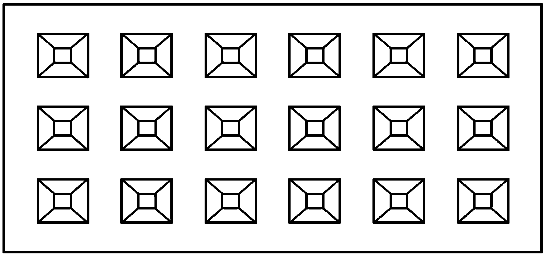
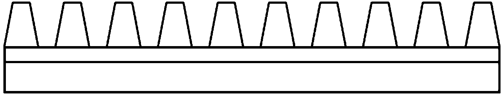
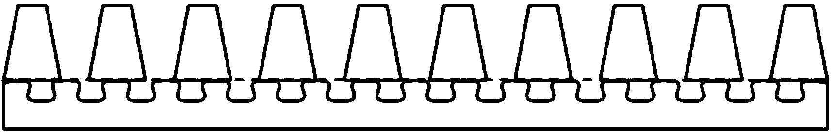
[0044] (3) The slurry that step (2) is obtained is coated on the template that has mold cavity on the surface (the shape of the mold cavity on the template: the inverted conical structure that truncated the top, size: upper surface size: 0.03mm*0.03 mm, the size of the lower surface: 0.45mm*0.45mm, the height of the ...

Embodiment 2

[0053] The used components of the adhesive of step (2) are as shown in table 3:

[0054] table 3

[0055]

[0056] (3) Apply the slurry obtained in step (2) to a template with a cavity on the surface (template size: cube structure, upper surface size: 0.45mm*0.45mm, lower surface size: 0.45mm*0.45mm, tower 0.45mm in height and 0.45mm in spacing) to form a slurry layer, then stick and press the pretreated substrate on the surface of the slurry layer, and then use ultraviolet light to cure for 24 hours and then release the mold to obtain a semi-finished product; The operation was the same as that in Example 1 to obtain a grinding tool with a cuboid structure protrusion. The continuous cutting force comparison diagram of the product with raised cuboid structure and the stepped product of embodiment 1 is as follows Figure 5 shown by Figure 5 It can be seen that under the same formula, the cutting force of the product is slightly different, which is related to the shape of ...

Embodiment 3

[0058] The used components of the adhesive of step (2) are as shown in table 4:

[0059] Table 4

[0060]

[0061] Other operations are identical with embodiment 1, and the result that obtains is as Figure 6 As shown, the results indicate that the cutting force decreased due to the change of the composition, and the durability was also reduced.


PUM

PropertyMeasurementUnit
particle diameteraaaaaaaaaa
sizeaaaaaaaaaa

Abstract

The invention discloses a manufacturing method of an anti-blocking grinding tool. The method includes the steps that firstly abrasive powder is added into adhesives and is fully dispersed, then bubbles are removed, and sizing agents are obtained; secondly, a template with the surface provided with a die cavity is coated with the sizing agents obtained in the first step, a sizing agent layer is formed, a preprocessed base material is attached and pressed to the surface of the sizing agent layer, ultraviolet light is used for solidification, die releasing is conducted, and a semi-finished product is obtained; thirdly, the semi-finished product obtained in the second step is solidified at the temperature of 80-90 DEG C, and the anti-blocking grinding tool is obtained. The invention further discloses the anti-blocking grinding tool manufactured through the manufacturing method, the anti-blocking grinding tool has the excellent chip removing capability in the use process, and ground chips can be effectively prevented from being accumulated and agglomerated.

Description

technical field [0001] The invention belongs to the field of precision grinding and polishing, and in particular relates to an anti-blocking grinding tool and a manufacturing method thereof. Background technique [0002] With the development of liquid crystal panel manufacturing, optical communication, automobile manufacturing and other technologies, the requirements for the related grinding and polishing fields are getting higher and higher. [0003] In the field of TFT-LCD liquid crystal panel manufacturing, as the panel is promoted to a higher generation and the touch screen technology is more and more widely used, the glass used in the panel is becoming thinner and stronger. In terms of liquid crystal glass thinning, due to the high requirements and high cost of transportation of large-size ultra-thin glass, LCD panel companies currently use thicker glass, which is thinned within the company before use. As for the thinning method of glass, the traditional CMP polishing ...

Claims


Application Information

Patent Timeline
Patent Type & Authority Applications(China)
IPC IPC(8): B24D18/00B24D3/28B24D11/00C09J163/10
Inventor 陈森军崔嘉敏
Owner 绍兴自远磨具有限公司
Why Eureka
Try Eureka