
Turbine condensate water heat recycling device

A technology of heat recovery and condensed water, which is applied in steam/steam condensers, lighting and heating equipment, etc., can solve the problem of difficult adjustment of shock absorber air pressure, avoid heat loss, have good thermal conductivity, and save manpower care costs Effect

Inactive Publication Date: 2021-03-23
甘信英
View PDF5 Cites 0 Cited by
  • Summary
  • Abstract
  • Description
  • Claims
  • Application Information

AI Technical Summary

Problems solved by technology

[0005] In order to solve the above-mentioned technical problems, the present invention provides a turbine condensate water heat recovery device that solves the problem that the air pressure of the traditional automobile shock absorber is difficult to adjust

Method used


Image

  • Turbine condensate water heat recycling device
  • Turbine condensate water heat recycling device
  • Turbine condensate water heat recycling device

Examples


Embodiment Construction

[0020] The present invention will be further described below in conjunction with the accompanying drawings and embodiments.

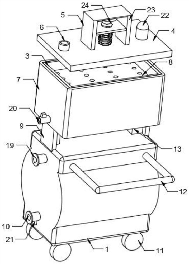
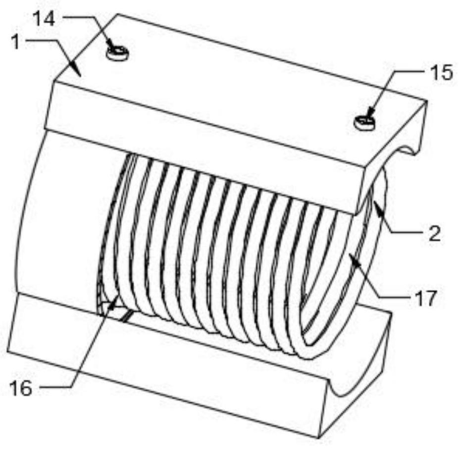
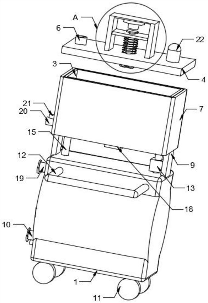
[0021] Please refer to figure 1 , figure 2 , image 3 with Figure 4 ,in, figure 1 A structural schematic diagram of a preferred embodiment of the turbine condensate heat recovery and utilization device provided by the present invention; figure 2 for figure 1 The schematic diagram of the overall connection structure shown; image 3 for figure 1 The schematic diagram of the internal connection structure of the fixed box is shown; Figure 4 for image 3 Schematic diagram of enlarged figure in A. The turbine condensate heat recovery and utilization device includes: a fixed box 1, a temperature sensor 18, a water level monitoring mechanism 5 and a heat recovery mechanism 2, the lower end of the side wall of the fixed box 1 is provided with a condensed water inlet 10, and the top of the side wall of the fixed box 1 Condensed water outlet 19 is pr...


PUM


Abstract

The invention provides a turbine condensate water heat recycling device. A condensate water inlet is formed in the lower end of the side wall of a fixed box, a condensate water outlet is formed in thetop end of the side wall of the fixed box, supporting plates are fixedly arranged on the two ends of the top of the fixed box, a storage box is installed at the tops of the supporting plates, a box cover is arranged at the top of the storage box, a clean water inlet is formed in one end of the top of the box cover, a water outlet is formed in the lower end of the storage box, a temperature sensoris installed at the bottom of the storage box, a probe of the temperature sensor extends into the storage box, a water level monitoring mechanism is arranged at the top of the box cover, and a heat recovery mechanism is arranged in the fixed box. According to the turbine condensate water heat recycling device, heat recycling is achieved, heat loss is effectively avoided, energy consumption is reduced, movement of the device can be achieved through the combined action of self-locking wheels and a push rod, the manpower nursing cost is reduced, and the situation that time and labor are wasted when personnel watch all the time is avoided.

Description

technical field [0001] The invention relates to the technical field of heat recovery and utilization devices, in particular to a heat recovery and utilization device for condensed water of a turbine. Background technique [0002] Turbines are commonly used in modern factories. Turbines are engines that use fluid to impinge on impeller rotation to generate power. In the production process of coal-fired power plants, turbines are required, and turbines will generate circulating condensed water during work. [0003] The temperature of the condensed water produced by the turbine is usually 28-45 degrees. The condensed water produced by the existing turbine is generally discharged directly, so that the temperature of the condensed water itself is lost, resulting in a waste of heat. The existing heat is recycled. The overall structure of the device is relatively fixed and rigid, which is not easy to move, consumes a large amount of labor, and increases the recycling cost. [0004...

Claims


Application Information

Patent Timeline
Patent Type & Authority Applications(China)
IPC IPC(8): F28B9/08F28B11/00
CPCF28B9/08F28B11/00
Inventor 甘信英陈锐
Owner 甘信英
Learn More