Supercharge Your Innovation With Domain-Expert AI Agents!

Depolarization compensation method of self-reference interferometer prism

A technology of self-referencing interference and compensation method, which is applied in the field of depolarization compensation of self-referencing interferometer prisms, which can solve the attenuation of outgoing light intensity, the difficulty of realizing prism rotation or changing the incident angle, and the solution of polarization-maintaining film coating, etc. question

Active Publication Date: 2021-03-23
INST OF MICROELECTRONICS CHINESE ACAD OF SCI
View PDF4 Cites 0 Cited by
  • Summary
  • Abstract
  • Description
  • Claims
  • Application Information

AI Technical Summary

Problems solved by technology

[0005] In the existing prism depolarization compensation method, there are often some disadvantages, such as the introduction of additional optical elements will lose the output light intensity, and it is difficult to realize the rotation of the prism or change the incident angle in some systems, and the solution of the polarization-maintaining film does not take into account the existing When there are multiple reflective surfaces and multiple reflections at different angles, the phase delay superposition between the reflective surfaces and the light intensity attenuation of the outgoing light have certain limitations.

Method used


Image

  • Depolarization compensation method of self-reference interferometer prism
  • Depolarization compensation method of self-reference interferometer prism
  • Depolarization compensation method of self-reference interferometer prism

Examples


Embodiment 1

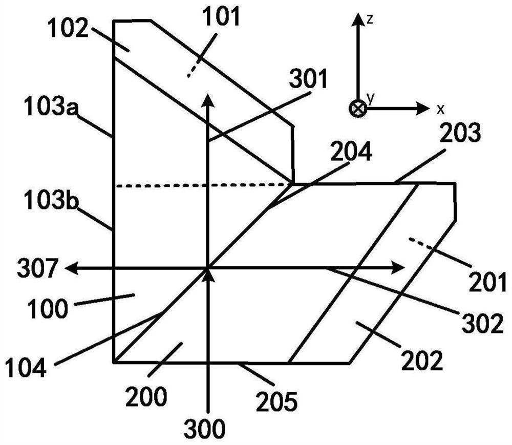
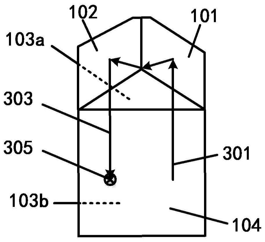
[0116] When the reflective film layer is a metal film, both n and κ are non-zero constants.

Embodiment 2

[0118] When the reflective film layer is a dielectric film, n is a non-zero constant and κ is zero.

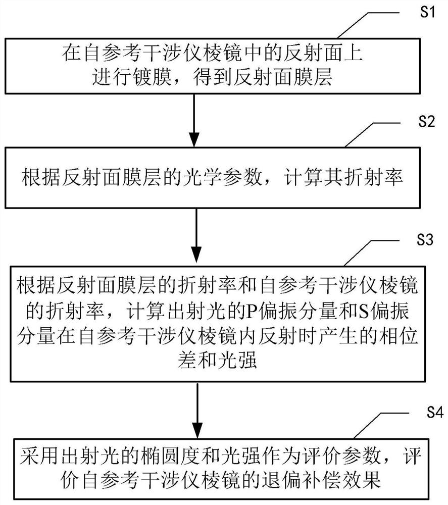
[0119] Step S3, when the incident light is incident on the interface between the self-referencing interferometer prism and the reflective film layer, it is decomposed into a P polarization component and an S polarization component, and according to the reflection coefficients of the P polarization component and the S polarization component, using the From the Jones matrix of the reference interferometer prism, the polarization tracking of the incident light is carried out, and the phase difference and light intensity generated when the P-polarized component and the S-polarized component of the outgoing light are reflected at the interface are calculated. Specifically include:

[0120] Step S31, when the incident light is incident on the interface between the self-referencing interferometer prism and the reflective film layer, the refraction angle θ t for

[0121]

[0122]...


PUM


Abstract

The invention provides a depolarization compensation method of a self-reference interferometer prism. The depolarization compensation method comprises the steps: plating a first ridge surface, a second ridge surface, a first bottom surface, a third ridge surface, a fourth ridge surface and a second bottom surface which serve as reflecting surfaces in the self-reference interferometer prism with reflecting surface film layers; calculating the refractive index of the reflective surface film layers according to the optical parameters of the reflective surface film layers; decomposing incident light into a P polarization component and an S polarization component when entering an interface of the self-reference interferometer prism and the reflective surface film layers, and calculating the phase difference and the light intensity generated by reflection of the P polarization component and the S polarization component of emergent light in the self-reference interferometer prism according tothe refractive indexes of the reflection surface film layers and the self-reference interferometer prism; and evaluating the depolarization compensation effect of the self-reference interferometer prism by taking the ovality and the light intensity of the emergent light as evaluation parameters. According to the invention, the Jones matrix of polarized light is used for tracing, the ovality and the light intensity of the emergent light are used as evaluation parameters, and thus the basis and the actual operability are provided for the optimization and effect evaluation of the parameters of the reflective surface film layers.

Description

technical field [0001] The disclosure relates to the field of integrated circuit manufacturing, in particular to a depolarization compensation method for a self-referencing interferometer prism. Background technique [0002] Systems that use optical methods to achieve high-precision measurement of displacement and position, such as laser interferometer displacement measurement systems, grating interferometer displacement measurement systems, and phase grating position measurement systems, etc., are mostly based on polarized light interference methods to achieve high measurement accuracy, and Often a large number of polarizing optics are required. In this type of optical system, it is very important to strictly control the polarization state of each part of the optical path, which often involves the influence of more complex prisms such as corner cube prisms, Bechan prisms, and self-referencing interferometer prisms on the polarization state. [0003] For example, in a phase...

Claims


Application Information

Patent Timeline
Patent Type & Authority Applications(China)
IPC IPC(8): G01B9/02G02B27/28
CPCG01B9/02072G02B27/285
Inventor 徐孟南卢增雄齐月静李璟谢冬冬马敬
Owner INST OF MICROELECTRONICS CHINESE ACAD OF SCI
Features
  • R&D
  • Intellectual Property
  • Life Sciences
  • Materials
  • Tech Scout
  • Unparalleled Data Quality
  • Higher Quality Content
  • 60% Fewer Hallucinations
Learn More