Detection device and method

A detection device and detection method technology, applied in the detection field, can solve the problems of long feedback time of detection results and low detection frequency

Pending Publication Date: 2021-03-23
梁金伟
View PDF0 Cites 0 Cited by
  • Summary
  • Abstract
  • Description
  • Claims
  • Application Information

AI Technical Summary

Problems solved by technology

[0003] The traditional detection method requires laboratory personnel to take samples to the site and bring them back to the laboratory for offline testing. The company needs to invest a lot of money to purchase related equipment, and the feedback time of test results is long and the detection frequency is low.

Method used


Image

  • Detection device and method
  • Detection device and method
  • Detection device and method

Examples


Embodiment 1

[0033] Example 1: Detection of miscellaneous oil content in fluids (eg, cleaning agents).

[0034] During the operation of the cleaning machine, various impurities will be mixed into the cleaning agent, and these impurities may include emulsified miscellaneous oil and / or water-soluble impurities. The inventor found through research that the most important influence on the cleaning effect is the content of miscellaneous oils. In addition, due to the complex composition of water-soluble impurities, the influence of different types of substances on the density is not the same, and the data obtained by only using the density meter to test the stock solution will have a large deviation.

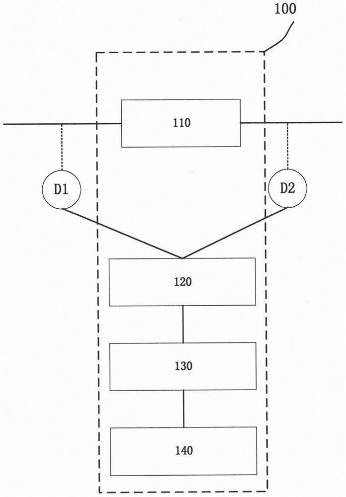
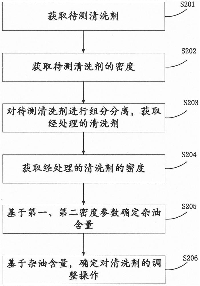
[0035] see also figure 1 , 2 ,in, figure 2 It is a flow chart of detecting miscellaneous oil according to an embodiment of the present invention.

[0036] Step S201: Obtain the cleaning agent to be tested.

[0037] In this step, the cleaning agent in use can be obtained as the cleaning agent...

Embodiment 2

[0050] Example 2: Detecting the content of solid particles and emulsified oil in the fluid.

[0051] Solid particles have the characteristics of large size and solid state, and emulsified oil has the characteristics of microscopic liquid and insoluble in water. Therefore, in this embodiment, the solid particles are filtered with the first filtration precision, thereby reducing the number of solid particles in the fluid; the emulsified oil is filtered with the second filtration precision, thereby reducing the content of the emulsified oil in the fluid. Due to the difference in the characteristics of solid particles and emulsified oil, when solid particles and emulsified oil exist in the stock solution at the same time, it is necessary to remove the solid particles first and then remove the emulsified oil.

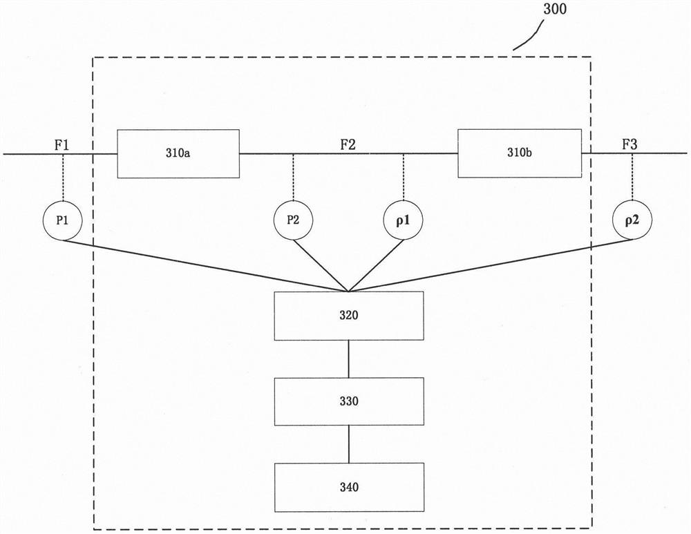
[0052] Figure 3a It is a structural diagram of a detection apparatus according to another embodiment.

[0053] The detection device 300 includes separation modules 310 a ...


PUM


Abstract

The present invention discloses a detection device. The detection device comprises a first separation module, a detection module, an analysis module and a control module; the first separation module is configured to adjust the content of a first component in a first fluid to obtain a second fluid, wherein the first fluid is obtained from a fluid to be detected; the detection module is configured to detect the first fluid and the second fluid to obtain a first detection result and a second detection result, wherein the first detection result represents the content of the first component in thefirst fluid, and the second detection result represents the content of the first component in the second fluid; the analysis module is configured to generate first operation information configured toadjust a state of the fluid to be measured based on a difference between the first detection result and the second detection result; and the control module is configured to adjust the state of the fluid to be measured based on an operation information set. According to the detection device and method provided by the technical schemes of the invention, the current state of the metal working fluid can be accurately detected, and the metal working fluid is adjusted based on the detection result.

Description

technical field [0001] The invention belongs to the field of detection, and in particular relates to a detection device and method for fluid. Background technique [0002] In the machining process of mechanical parts, different metalworking fluids are required at different stages, such as cutting emulsions, cutting oils, stamping oils, quenching fluids, aqueous cleaning fluids, organic cleaning solvents, polishing fluids, etc. During the use of metalworking fluids, contaminants, such as oily contaminants, solid contaminants, and water-soluble contaminants, are often mixed in. Contaminants will affect the efficiency and service life of metalworking fluids, and in severe cases will cause metalworking fluids to fail. At present, in order to exert the performance of metalworking fluids and prolong the service life, it is necessary to conduct a number of tests on metalworking fluids during use, including pH value, conductivity, concentration, oil content, alkali value, acid valu...

Claims


Application Information

Patent Timeline
Patent Type & Authority Applications(China)
IPC IPC(8): G01N33/00G05D27/02
CPCG01N33/00G05D27/02
Inventor 梁金伟
Owner 梁金伟
Why Eureka
Try Eureka