Thread bolt, fixator, thread bolt operating device and using method
A technology for fixers and thread bolts, applied in the field of thread bolt operating devices, fixers, and thread bolts, can solve the problems of affecting the field of thread bolts, increasing the difficulty of modeling, and being unable to continue to use, so as to avoid the effect of blood backflow out of the thread bolts
- Summary
- Abstract
- Description
- Claims
- Application Information
AI Technical Summary
Problems solved by technology
Method used
Image
Examples
Embodiment 1
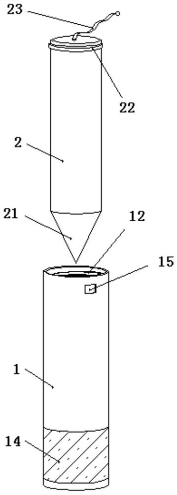
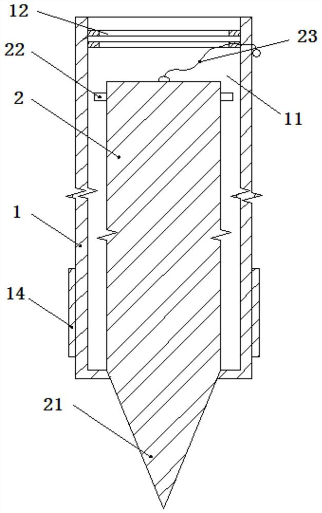
[0034] refer to figure 1 with figure 2 As shown, an embodiment of a wire bolt of the present invention includes a bolt tube 1 and an insertion rod 2 placed inside the bolt tube 1 , and the insertion rod 2 includes a tip 21 at its end. An accommodating chamber 11 penetrates through the inside of the plug tube 1 along its axial direction, and the insertion rod 2 is placed in the accommodating chamber 11 , and the axial direction of the insertion rod 2 and the axial direction of the plug tube 1 are substantially collinear. The insertion rod 2 placed in the plug tube 1 can move relative to the plug tube 1 along its axial direction, so that the insertion rod 2 can be completely retracted into the inside of the plug tube 1, and the tip 21 at the end of the insertion rod 2 can also be moved from the plug Tube 1 sticks out inside. When the tip 21 protrudes from the inside of the bolt tube 1, and at this time the insertion rod 2 can be relatively fixed with the bolt tube 1 to realiz...
Embodiment 2
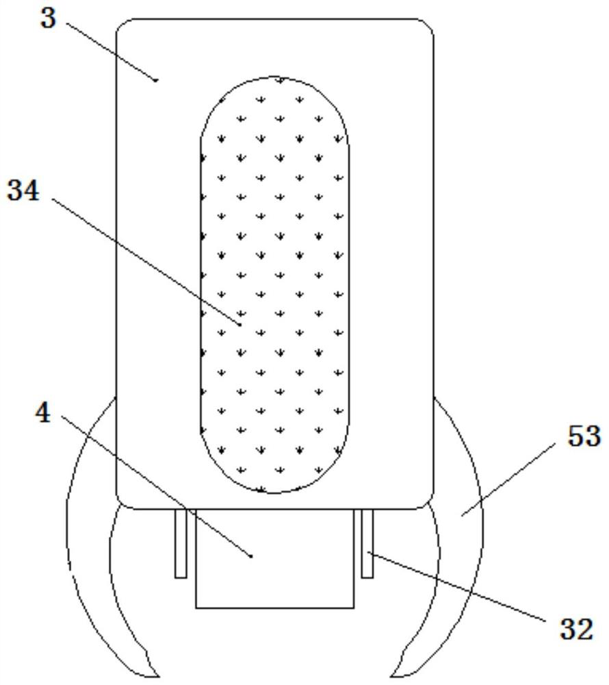
[0043] a fixer, see Figure 3-Figure 5 , for adapting to the above-mentioned wire bolt, which includes a main body 3 and an abutment section 4, and the abutment section 4 is connected to the main body 3 through a linkage section. The linkage section is used to adjust the position of the abutment section 4 relative to the main body 3, and the abutment section 4 is used to contact and push the insertion rod 2, so when the main body 3 adjusts the position of the abutment section 4 relative to the main body 3 through the linkage section, the The abutting section 4 that the plunger 2 contacts will adjust the position of the plunger 2 relative to the plug tube 1 , so as to push the tip 21 out of the plug tube 1 .
[0044] The linkage section includes a first elastic member 51 , a first connecting rod 52 and at least one set of locking members 53 , the first connecting rod 52 is connected to the main body 3 through the first elastic member 51 , and the first connecting rod 52 is conn...
Embodiment 3
[0050] a fixer, see Image 6 with Figure 7 Compared with the second embodiment, the difference is that the linkage section includes a second elastic member 61, a second connecting rod 62 and a locking bolt 63, the second connecting rod 62 is connected to the main body 3 through the second elastic member 61, and the second connecting rod The rod 62 is connected to the abutment section 4; the bolt tube 1 is provided with a first communication hole 13 that cooperates with the locking bolt 63, and the abutment section 4 is provided with a group of second communication holes 41 that cooperate with the locking bolt 63; the locking bolt 63 can Through the first communication hole 13 and the second communication hole 41 , preferably, the diameter of the first communication hole 13 is slightly larger than the diameter of the second communication hole 41 and the diameter of the locking bolt 63 .
[0051] When the main body 3 is pressed down, the second connecting rod 62 will press the...
PUM
| Property | Measurement | Unit |
|---|---|---|
| Length | aaaaa | aaaaa |
| Length | aaaaa | aaaaa |
Abstract
Description
Claims
Application Information
 - R&D Engineer
- R&D Manager
- IP Professional
- Industry Leading Data Capabilities
- Powerful AI technology
- Patent DNA Extraction
Browse by: Latest US Patents, China's latest patents, Technical Efficacy Thesaurus, Application Domain, Technology Topic, Popular Technical Reports.
© 2024 PatSnap. All rights reserved.Legal|Privacy policy|Modern Slavery Act Transparency Statement|Sitemap|About US| Contact US: help@patsnap.com


