Slitting machine capable of adjusting feeding width and length of steel sheet coiled material
An adjustable, slitting machine technology, applied in the direction of shearing devices, shearing machine accessories, metal processing equipment, etc., can solve the problems of no power setting for the cutter, difficulty in cutting steel sheets, inconvenient adjustment, etc., to achieve guaranteed The effect of uniformity
- Summary
- Abstract
- Description
- Claims
- Application Information
AI Technical Summary
Problems solved by technology
Method used
Image
Examples
Embodiment 1
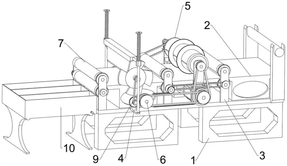
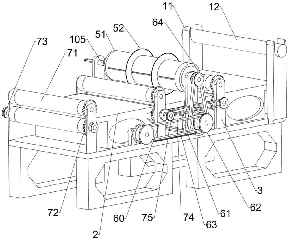
[0029] A steel sheet coil feeding width and length adjustable slitting machine, such as Figure 1 to Figure 3 As shown, it includes a base 1, a mounting plate 2, a first mounting frame 3, a second mounting frame 4, a cutting mechanism 5, a power mechanism 6, and a feeding mechanism 7. The top of the base 1 is connected to the mounting plate 2, and the top of the base 1 is evenly spaced There are three first mounting frames 3 connected to the ground, and a second mounting frame 4 is installed on the front and rear sides of the left part of the base 1. A cutting mechanism 5 is installed in the middle of the top of the mounting plate 2, and a power is connected between the base 1 and the cutting mechanism 5. Mechanism 6, a feeding mechanism 7 is installed on the first installation frame 3, and the feeding mechanism 7 is connected with the power mechanism 6 through transmission.
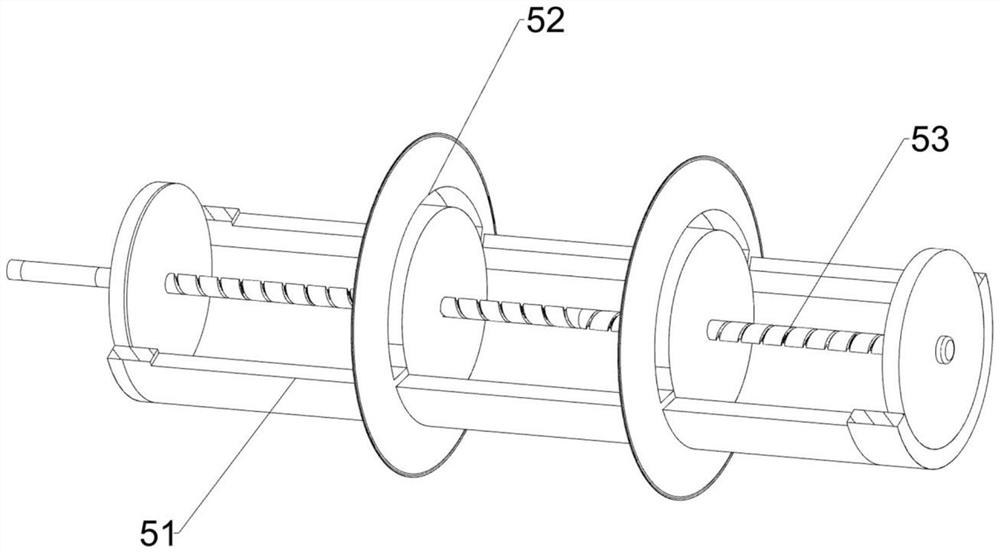
[0030] The cutting mechanism 5 includes a drum 51, a cutting knife 52 and a first two-way screw 53. T...
Embodiment 2
[0035] On the basis of Example 1, such as Figure 4 As shown, also include cross-cutting mechanism 8, and cross-cutting mechanism 8 includes guide bar 81, knife rest 82, back-moving spring 83, cutter 84, fixed frame 85 and one-way convex plate 86, the second installation of front and rear sides All are connected with guide rod 81 on the frame 4, between the guide rod 81 of front and back both sides slide type is connected with knife rest 82, is connected with back-moving spring 83 between knife rest 82 and guide rod 81 tops, and knife rest 82 bottoms are equipped with Cutter 84 is connected with fixed mount 85 on the left side front portion of mounting plate 2, and on fixed mount 85, one-way convex disc 86 is installed in a rotatable manner, and one-way convex disc 86 contacts and cooperates with knife rest 82.
[0036] Also includes a power linkage mechanism 9, the power linkage mechanism 9 includes a second gear 91, a chain drive assembly 92 and a second toothed belt 93, the s...
Embodiment 3
[0039] On the basis of Example 2, such as figure 2 , Figure 5 with Image 6 As shown, a charging mechanism 10 is also included, and the charging mechanism 10 includes a charging box 101, a dividing plate 102, a second two-way screw 103, a fourth belt drive group 104, a first internal diamond sleeve 105, and a diamond rod 106 And the second inner rhombus sleeve 107, the left side of base 1 is connected with charging box 101, is connected with two dividing plates 102 slidingly in charging box 101, and is connected with the rotatable in charging box 101 the first Two two-way screws 103, the second two-way screw 103 runs through two partitions 102, the partition 102 is threadedly connected with the second two-way screw 103, the rear side middle part of the mounting plate 2 is connected with the first inner diamond sleeve 105 in a rotational manner, the second A rhombus sleeve 105 is slidably connected with a rhombus rod 106, the rear end of the first two-way screw 53 is connec...
PUM
 Abstract
Description
Claims
Application Information
 - R&D
- Intellectual Property
- Life Sciences
- Materials
- Tech Scout
- Unparalleled Data Quality
- Higher Quality Content
- 60% Fewer Hallucinations
Browse by: Latest US Patents, China's latest patents, Technical Efficacy Thesaurus, Application Domain, Technology Topic, Popular Technical Reports.
© 2025 PatSnap. All rights reserved.Legal|Privacy policy|Modern Slavery Act Transparency Statement|Sitemap|About US| Contact US: help@patsnap.com


