Flexible actuator driven by chemical energy release reaction

A technology of energy release reaction and actuator, applied in the field of robotics, can solve problems such as fast motion performance and load capacity defects

Active Publication Date: 2021-03-26
ZHEJIANG UNIV
View PDF6 Cites 2 Cited by
  • Summary
  • Abstract
  • Description
  • Claims
  • Application Information

AI Technical Summary

Problems solved by technology

However, all kinds of flexible actuators currently available cannot produce fast motion performance. At the same time, because some or all of them are made of flexible materials, they have relatively large defects in load capacity.

Method used


Image

  • Flexible actuator driven by chemical energy release reaction
  • Flexible actuator driven by chemical energy release reaction
  • Flexible actuator driven by chemical energy release reaction

Examples


Embodiment 1

[0029] As shown in the figure, a flexible actuator driven by a chemical release energy reaction, including

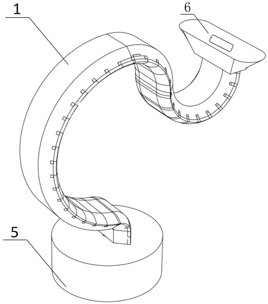
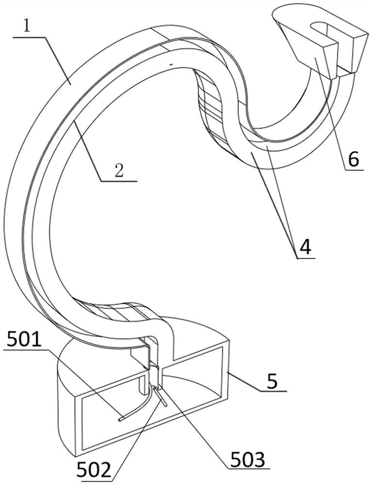
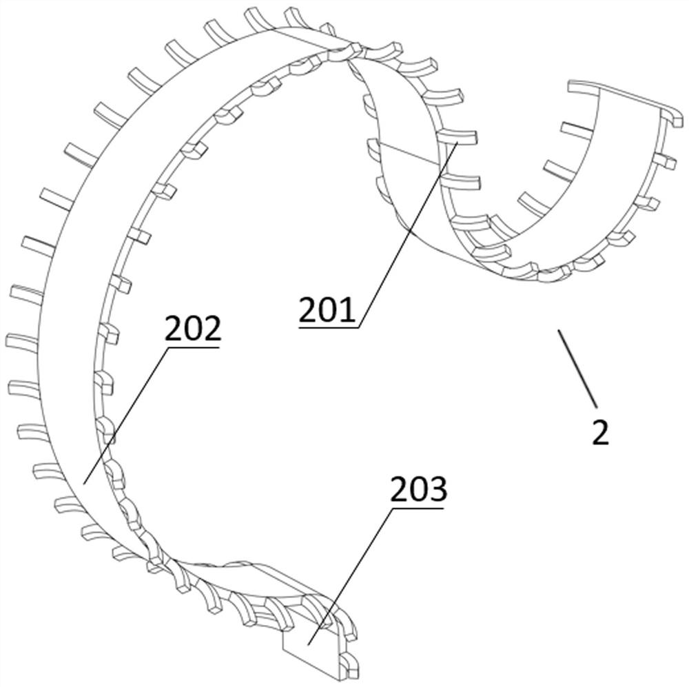
[0030] The main body of the actuator, the actuator body includes an execution skeleton 2 and a flexible execution membrane 1, the flexible execution membrane 1 has a hollow fluid passage 4 inside, the execution skeleton 2 is arranged in it along the length direction of the hollow fluid passage 4 and the hollow fluid passage 4 Separated into front and rear parts;

[0031] Execution terminal 6, the execution terminal 6 is arranged on the upper end of the executor body, which is used to complete the command to be executed; and

[0032] The base 5, the base 5 is used to fix the lower end of the actuator body, and a gas source module 501 and an excitation module 502 are arranged inside, the gas source module 501 is used to provide fuel gas for the hollow fluid channel 4, and the excitation module 502 is used to ignite The fuel gas input into the hollow fluid passage 4 makes...

Embodiment 2

[0044] The difference between this embodiment and Embodiment 1 lies in that the rigidity of the front side surface of the flexible actuator membrane 1 is smaller than that of the rear side surface.

[0045] by Figure 6 , 7 The shown example explains the contact motion principle of a flexible actuator based on chemical reaction technology. The surface stiffness of the rear side of the flexible actuator membrane 1 is set to be higher than the stiffness of the front side surface, fuel gas is continuously input into the front and rear parts of the hollow fluid channel 4 through the gas source module 501, and the injected fuel gas is ignited through the excitation module 502 , an extremely high pressure is generated instantaneously, and the gas pressure acts on the inner surface of the flexible executive membrane 1. Due to the difference in stiffness, the deformation of the front side surface of the flexible executive membrane 1 is much larger than that of the rear side surface, ...

Embodiment 3

[0047] The difference between this embodiment and Embodiments 1 and 2 is that the rigidity of the front side surface of the flexible executive membrane 1 is the same as that of the rear side surface.

[0048] In this embodiment, when the projectile action is performed, more fuel gas is passed into the rear part of the hollow fluid channel 4 through the gas source module 501. The rear side of the flexible actuator membrane 1 produces greater deformation, which drives the actuator body to make a projectile action; when the object is contacted in this embodiment, more air is injected into the front side of the hollow fluid channel 4 through the air source module 501. Both parts of the fuel gas continue to input fuel gas, and the fuel gas passed through is ignited by the excitation module 502, causing greater deformation of the front side of the flexible actuator membrane 1, and driving the actuator body to make a contact action.


PUM


Abstract

The invention belongs to the field of robots, and particularly relates to a flexible actuator driven by chemical energy release reaction. The flexible actuator driven by chemical energy release reaction comprises an actuator body, an actuating terminal and a base, the actuator body comprises an actuating framework and a flexible actuating film, and a hollow fluid channel is formed in the flexibleactuating film. The actuating framework is arranged in the hollow fluid channel in the length direction of the hollow fluid channel and divides the hollow fluid channel into a front part and a rear part, the actuating terminal is used for completing a command to be executed, the base is used for fixing the lower end of the actuator body, and an air source module and an excitation module are arranged in the base. According to the flexible actuator, chemical energy release reaction and variable stiffness structure design are creatively combined, movement of a flexible end effector driven by thechemical energy release reaction is achieved, and simulation of the end effector is achieved through variable stiffness manufacturing and overlapping design; and a variable stiffness structure is innovatively used to simulate the skeleton structure of the end effector, and a flexible membrane structure is used to coat the skeleton.

Description

technical field [0001] The invention belongs to the field of robots, and in particular relates to a flexible actuator driven by chemical discharge energy reaction. Background technique [0002] As a widely developed automatic execution device, the automatic execution terminal can execute the expected movement target in the program control mode, among which the mechanical arm is the representative, which has the advantages of high speed, accuracy and strong load capacity. However, due to its large size and weight, rigid actuators have major defects in carrying, setting, and assembly. Therefore, flexible actuators have become a potential development direction for automated actuators. Flexible execution ends (such as flexible grippers, flexible fingers, or flexible suction cups, etc.) have become a hot research direction in the field of robotics in recent years because of their high degree of freedom, high quality, and good user interaction. The driving methods of the flexible...

Claims


Application Information

Patent Timeline
Patent Type & Authority Applications(China)
IPC IPC(8): B25J9/10B25J9/00
CPCB25J9/1095B25J9/0015
Inventor 焦鹏程杨旸王海鹏贺治国
Owner ZHEJIANG UNIV
Why Eureka
Try Eureka