Rubber product processing device

A technology for processing devices and rubber products, applied in metal processing and other directions, can solve problems such as inability to achieve precise drilling, and achieve the effects of high efficiency, improved accuracy, and improved applicability

Inactive Publication Date: 2021-03-26
南陵县巍曙新材料科技有限责任公司
View PDF1 Cites 3 Cited by
  • Summary
  • Abstract
  • Description
  • Claims
  • Application Information

AI Technical Summary

Problems solved by technology

[0006] Aiming at the deficiencies of the prior art, the present invention provides a rubber product processing device, which solves the problem that precision punching cannot be realized, improves the accuracy of the device, has higher efficiency, and also improves the applicability of the punching device. It is more economical and efficient, and achieves the purpose of clamping rubber products, effectively preventing accidents caused by rubber products falling off due to vibration

Method used


Image

  • Rubber product processing device
  • Rubber product processing device
  • Rubber product processing device

Examples


Embodiment 1

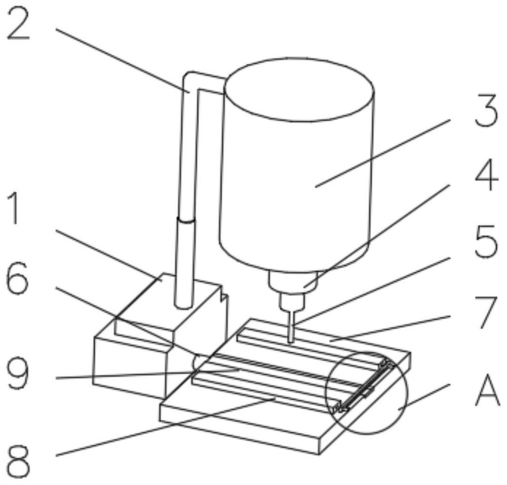
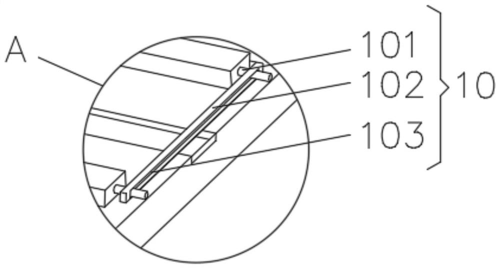
[0031] see Figure 1-2 , the present invention provides a technical solution: a rubber product processing device, including a base 1, a telescopic rod 2 is fixedly connected to the top of the base 1, a motor 3 is installed on the end of the telescopic rod 2 away from the base 1, and the output shaft of the motor 3 rotates Connected with a rotating rod 4, the end of the rotating rod 4 away from the motor 3 is equipped with a drill bit 5, one side of the base 1 is fixedly connected with a positioning plate 7 through a connecting rod 6, and the side of the positioning plate 7 near the drill bit is equipped with a clamping plate 8, A reinforcing plate 9 is fixedly connected to the side of the positioning plate 7 close to the clamping plate 8 , and a clamping device 10 is installed on the side of the clamping plate 8 away from the connecting rod 6 .

[0032] The clamping device 10 includes a threaded rod 101, one end of the threaded rod 101 is fixedly connected with the clamping pl...

Embodiment 2

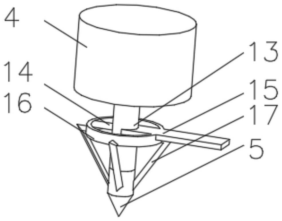
[0035] see Figure 1-5 , the present invention provides a technical solution: on the basis of Embodiment 1, an extension rod 12 is installed on the side of the drill bit 5 close to the rotating rod 4, and the end of the extension rod 12 away from the drill bit 5 is fixedly connected with a hollow rotating shaft 13, and the hollow rotating shaft 13 The outer side of the hollow rotating shaft 13 is rotatably connected with a connecting column 14, and the side of the hollow rotating shaft 13 away from the connecting column 14 is rotatably connected with a scale 15. The end of the connecting column 14 away from the hollow rotating shaft 13 is equipped with a rubber ring 16, and the side of the rubber ring 16 is away from the connecting column. The position of 14 is slidingly connected with scale 15, and the outer bottom of rubber ring 16 is rotatably connected with moving bar 17.

[0036] The inside of the drill bit 5 is equipped with an adjustment device 11, the adjustment device...

Embodiment 3

[0040] see Figure 1-6 , the present invention provides a technical solution: on the basis of Embodiment 2, a groove 19 is provided at one end of the adjustment rod 115 close to the slider 113, a spring 20 is installed on the inner wall of the groove 19, and one end of the spring 20 is fixedly connected with a buffer Block 21, one end of the buffer block 21 is connected with the adjusting rod 115, and the rubber block 22 is symmetrically installed on the side of the buffer block 21 near the spring.

[0041] During use, the moving rod 17 drives the adjusting rod 115 to move, and the adjusting rod 115 is pushed to extrude the spring 20 to move toward the buffer block 21. The rubber block 22 installed on one side of the buffer block 21 touches the inner wall of the groove 19, and the buffer block and The installation of the spring achieves the effect of buffering and damping the adjustment rod, and improves the service life of the device.


PUM


Abstract

The invention discloses a rubber product processing device which comprises a base. A telescopic rod is fixedly connected to the top of the base, so that the purpose of vertically adjusting a drill bitis achieved; a motor is installed at the end, away from the base, of the telescopic rod, a rotating rod is rotatably connected to an output shaft of the motor, and the drill bit is installed at the end, away from the motor, of the rotating rod; a positioning plate is fixedly connected to one side of the base through a connecting rod, a clamping plate is installed at the side, close to the drill bit, of the positioning plate, and a reinforcing plate is fixedly connected to the side, close to the clamping plate, of the positioning plate, so that the situation that the positioning plate is accidentally abraded when the drill bit punches holes is reduced; and a clamping device is mounted at the side, away from the connecting rod, of the clamping plate. The invention relates to the technical field of rubber product processing. According to the rubber product processing device, the purpose of adjusting the hole diameter when a rubber product is punched is achieved, then the applicability ofa punching device is improved, and the rubber product processing device is more economical and efficient.

Description

technical field [0001] The invention relates to the technical field of rubber product processing, in particular to a rubber product processing device. Background technique [0002] The rubber stopper is a kind of sealing device used in chemical experiments. Since it is often necessary to insert a glass tube to form a connecting device during use, it is often necessary to use a puncher to punch holes. The most commonly used hole puncher is a hollow drill rod at present, and one end both sides of drill rod extend outwards as handle, and the other end is a circular opening, and an iron bar is also arranged in the middle. When punching a hole, choose a hole punch that is slightly thicker than the glass tube to be inserted into the rubber stopper. Put the small end of the stopper upwards and place it on a stable table. Hold the stopper with your left hand and press the handle of the hole puncher with your right hand. At the selected location, drill down vertically in one directi...

Claims


Application Information

Patent Timeline
Patent Type & Authority Applications(China)
IPC IPC(8): B26D7/02B26D7/26B26D7/28B26F1/16
CPCB26D7/02B26D7/2628B26D7/28B26F1/16
Inventor 黄云
Owner 南陵县巍曙新材料科技有限责任公司
Why Eureka
Try Eureka