Automatic circle cutting device for wooden grate for food steamer

A grate and wooden technology, which is applied in the field of automatic round cutting device for wooden grates for steamers, can solve the problems of inability to realize automatic round cutting, rounding of wooden grates, and poor quality of finished products, so as to achieve good round cutting effect, improve work efficiency, and automate high degree of effect

Active Publication Date: 2021-03-26
山东聊城鼎诚激光设备有限公司
View PDF8 Cites 0 Cited by
  • Summary
  • Abstract
  • Description
  • Claims
  • Application Information

AI Technical Summary

Problems solved by technology

[0006] In order to overcome the disadvantages that the two ends of the wooden sticks need to be trimmed one by one by cutting tools, the present invention is inefficient, and it is difficult to round the wooden grate, resulting in poor quality of the finished product and the inability to realize automatic round cutting. The technical problem is to provide an automatic round cutting device for wooden grates for steamers that can improve the cutting efficiency of wooden grates, improve the quality of finished products, and have a high degree of automation

Method used


Image

  • Automatic circle cutting device for wooden grate for food steamer
  • Automatic circle cutting device for wooden grate for food steamer
  • Automatic circle cutting device for wooden grate for food steamer

Examples


Embodiment approach 1

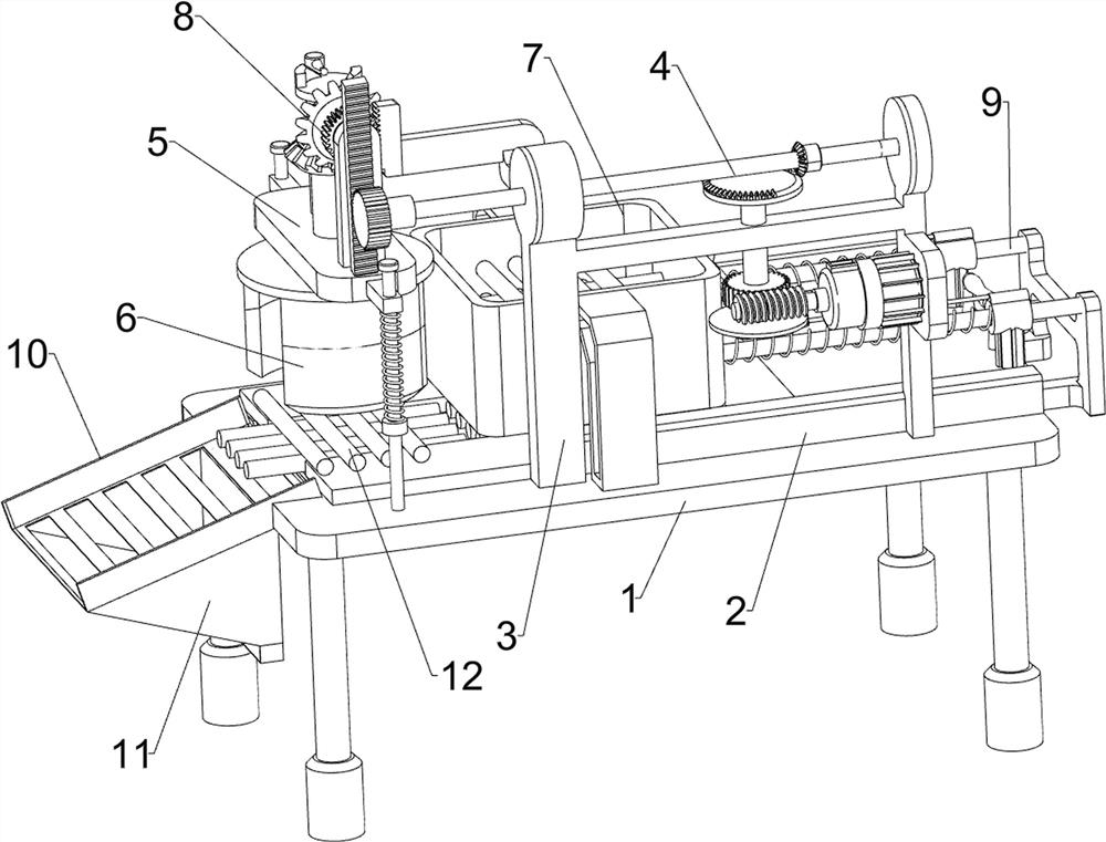
[0028] A wooden grate automatic circle cutting device for steamer, please refer to Figure 1 to Figure 3 As shown, it includes a frame 1, a guide plate 2, a mounting frame 3, a power mechanism 4, an elevating mechanism 5 and a cutting assembly 6. The guide plate 2 is installed in the middle of the top of the frame 1, and the top front side of the frame 1 is connected with a Mounting frame 3, power mechanism 4 is installed on the mounting frame 3, elevating mechanism 5 is installed on the left side of frame 1 top, elevating mechanism 5 and power mechanism 4 transmission cooperates, and cutting assembly 6 is installed on the elevating mechanism 5.

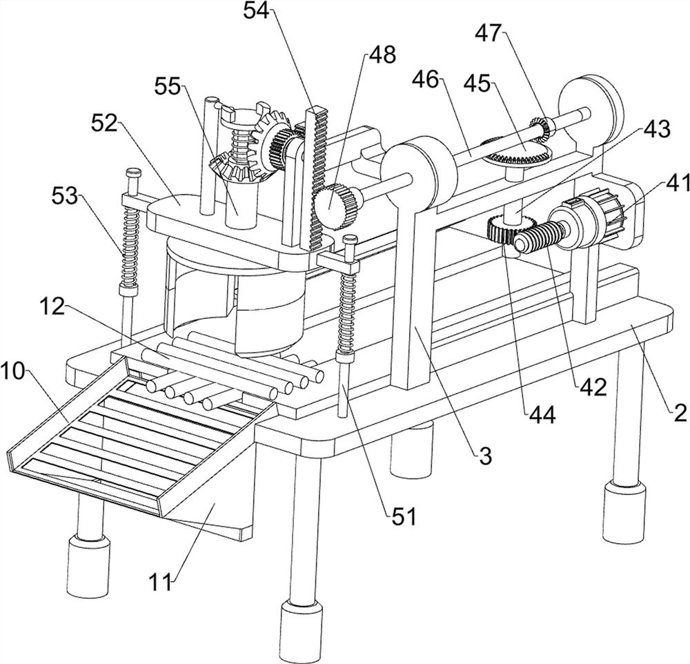
[0029] The power mechanism 4 includes a servo motor 41, a worm screw 42, a first rotating shaft 43, a worm wheel 44, a three-quarter missing bevel gear 45, a second rotating shaft 46, a first bevel gear 47 and a sector gear 48, and the right side of the mounting frame 3 Servomotor 41 is installed, and the output shaft of servomotor 4...

Embodiment approach 2

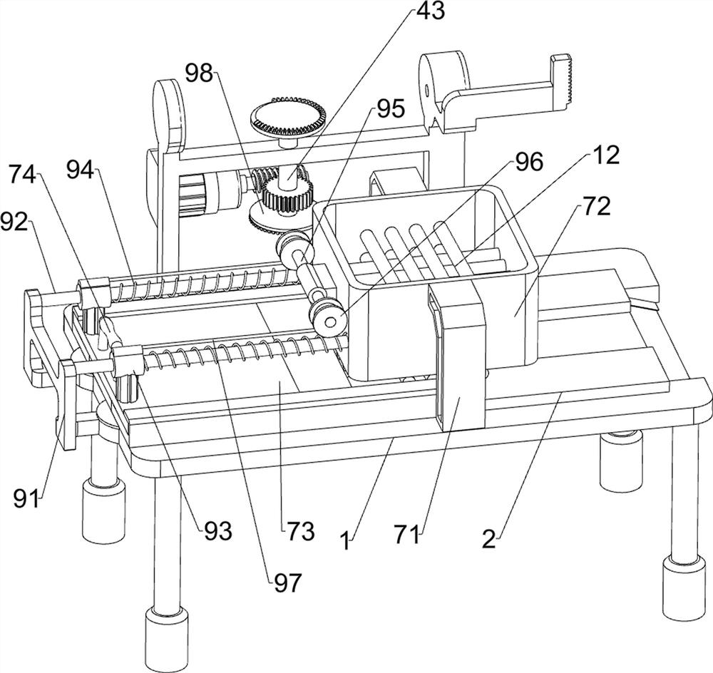
[0034] On the basis of Embodiment 1, please refer to image 3 and Figure 4 As shown, it also includes a feeding assembly 7, and the feeding assembly 7 includes a connecting frame 71, a material blocking frame 72, a push plate 73 and a handle 74, and two connecting frames 71 are installed in the middle of the top of the frame 1, and the two connecting frames 71 are in the form of Front and back are arranged symmetrically, a material retaining frame 72 is connected between the two connecting frames 71, a push plate 73 is slidably connected to the right part of the guide plate 2, and a handle 74 is connected to the right end of the top of the push plate 73.

[0035] Place the wooden frame 12 in the material retaining frame 72, and the bottom wooden frame 12 is in contact with the top of the frame 1. When the wooden frame 12 needs to be cut, manually hold the handle 74 and push it to the left, and the push plate 73 will move to the left accordingly. Move to the left, the push pl...

Embodiment approach 3

[0039] On the basis of the second implementation mode, please refer to figure 1 , Figure 4 and Figure 5 As shown, it also includes a pusher linkage mechanism 9, and the pusher linkage mechanism 9 includes a fixed frame 91, a transverse guide rod 92, a sliding sleeve 93, a compression spring 94, a connecting shaft 95, a winding reel 96, a backguy 97, a quarter One tooth-missing bevel gear 98 and the second bevel gear 99, the right end of the frame 1 is connected with a fixed frame 91, two horizontal guide rods 92 are horizontally connected between the fixed frame 91 and the retaining frame 72, and the two horizontal guide rods 92 It is symmetrically arranged front and back, and a sliding sleeve 93 is slidably connected to the horizontal guide rod 92, the bottom of the sliding sleeve 93 is connected with the top of the push plate 73, and a compression spring 94 is connected between the sliding sleeve 93 and the retaining frame 72, and the compression spring 94 Sleeved on the...


PUM


Abstract

The invention relates to a circle cutting device, in particular to an automatic circle cutting device for a wooden grate. The technical problem to be solved is to provide the automatic circle cuttingdevice for the wooden grate for a food steamer, wherein the automatic circle cutting device can improve the circle cutting efficiency of the wooden grate and the quality of a finished product and is high in automation degree. In order to solve the above technical problem, the automatic circle cutting device for the wooden grate for the food steamer comprises a rack, a mounting frame, a power mechanism, a lifting mechanism, and a cutting assembly, wherein a guide plate is mounted at the top of the machine frame, the mounting frame is fixedly connected to the rack, the power mechanism is mountedon the mounting frame, the lifting mechanism is connected to one side of the top of the rack, the lifting mechanism is in transmission fit with the power mechanism, and the cutting assembly is connected to the lifting mechanism. According to the automatic circle cutting device, through cooperation of the power mechanism, the lifting mechanism and the cutting assembly, a wooden frame can be cut into a circle, people do not need to cut off the wood frame one by one through a cutter, the circle cutting effect is good, and the efficiency is high.

Description

technical field [0001] The invention relates to a circle cutting device, in particular to an automatic circle cutting device for a wooden grate for a steamer. Background technique [0002] The most important appliance for steaming buns is the steamer. At present, there are many materials for the steamer, including bamboo, wood, and stainless steel. Among them, wooden steamers are widely used, and a wooden grate needs to be placed inside the wooden steamer. Used to place buns. [0003] At present, when the wooden grate is made, it is usually combined with small wooden rollers to form a shelf, and then trimmed into a circle with a knife. In this way, the two ends of the stick need to be trimmed one by one, which is inefficient, and Difficulty rounding wooden grates, resulting in poor quality finished products, and automatic round cutting is not possible. [0004] Therefore improve the round cutting efficiency of wooden grate, improve the quality of finished product, realize ...

Claims


Application Information

Patent Timeline
IPC IPC(8): B27M3/24B27C5/00
CPCB27M3/24B27C5/00
Inventor 严业松
Owner 山东聊城鼎诚激光设备有限公司
Why Eureka
Try Eureka