Metal strip flame heating device and heating method thereof

A metal strip and flame heating technology, applied in heat treatment furnaces, heat treatment equipment, furnaces, etc., can solve the problems of large energy consumption, inability to achieve energy storage effects, and inability to achieve uniform heating

Active Publication Date: 2022-06-24
OKUMTEC TECH WENZHOU CO LTD
View PDF0 Cites 0 Cited by
  • Summary
  • Abstract
  • Description
  • Claims
  • Application Information

AI Technical Summary

Problems solved by technology

[0003] The purpose of the present invention is to solve the disadvantages in the prior art that the effect of uniform heating cannot be achieved, and at the same time the effect of energy storage cannot be achieved, so that the energy consumption is relatively large, and a metal strip flame heating device and its heating method are proposed.

Method used


Image

  • Metal strip flame heating device and heating method thereof
  • Metal strip flame heating device and heating method thereof
  • Metal strip flame heating device and heating method thereof

Examples


Embodiment 1

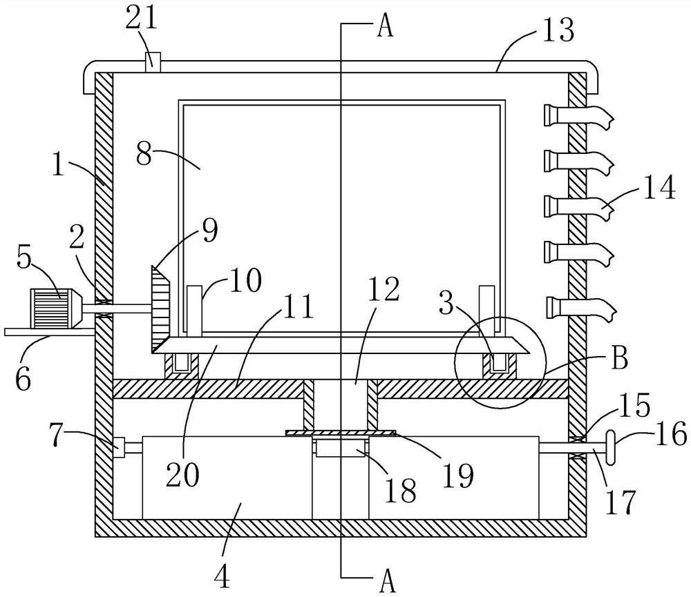
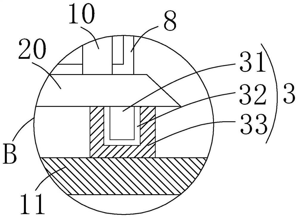
[0024] refer to Figure 1-4 , a metal plate with flame heating device, including a casing 1, the upper end of the casing 1 is screwed with an upper cover 13, the upper end of the upper cover 13 is installed with a gas pipe 21 penetrating the upper cover 13, and the gas pipe 21 can prevent the casing The heat inside the 1 increases, which causes the upper cover 13 to be subjected to a large lifting force, resulting in wear of the upper cover 13 .

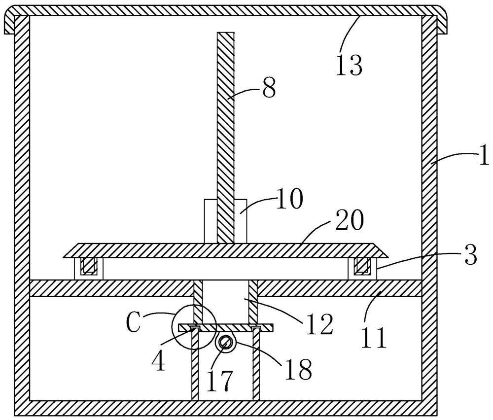
[0025] A fixed plate 11 is horizontally welded to the lower end of the inner side of the housing 1, and the lower end of the fixed plate 11 is provided with a temperature storage mechanism. The moving mechanism includes a shaft seat 7 fixedly installed on one side of the lower end of the casing 1 and a sealed bearing 15 installed on the other side of the lower end of the casing 1 . , one end of the threaded rod 17 extends to the inner side of the shaft seat 7, and the threaded rod 17 is also threadedly connected with a threaded slee...

Embodiment 2

[0033] refer to figure 1 , as another preferred embodiment of the present invention, the difference from Embodiment 1 is that the gear plate 20 and the middle end of the outer side of the casing 1 are provided with a power mechanism, and the power mechanism includes a fixed installation on the outer side of the casing 1. The support plate 6 and the bearing 2 installed in the middle part of one side of the housing 1, the upper end of the support plate 6 is fixed with a stepping motor 5 by screws, and the output shaft of the stepping motor 5 penetrates the bearing 2 and extends to the inner side of the housing 1, The main gear 9 is installed vertically at the end of the output shaft of the stepping motor 5 inside the housing 1, and the main gear 9 and the gear plate 20 are meshed with each other. External control switch, the stepper motor 5 drives the main gear 9 to rotate, and the main gear 9 and the gear plate 20 are meshed with each other, so that the gear plate 20 rotates in...


PUM


Abstract

The invention relates to the technical field of metal strip processing, in particular to a metal strip flame heating device, which includes a shell, the upper end of the shell is threadedly connected with an upper cover, and one side of the upper end of the upper end is installed with a penetrating upper cover The upper end of the fixed plate is provided with a rotating mechanism, and a gear plate is horizontally fixed by the rotating mechanism, and a plurality of flame injector bodies penetrating through the casing are installed on the upper end of the other side of the outer side of the casing. One end of the injector body is connected to the gas supply device through a connecting pipe, and two splints are fixed in parallel on both sides of the upper end of the fixing plate, and a metal plate is clamped and fixed between a plurality of the splints. The present invention achieves the effect of uniform heating under the state of stably clamping the metal strip, and at the same time can achieve the effect of energy storage, so that when the plate is heated here, the stored energy can be utilized.

Description

technical field [0001] The invention relates to the technical field of metal plate and strip processing, in particular to a metal plate and strip flame heating device and a heating method thereof. Background technique [0002] After the metal sheet and strip are processed, heat treatment is required, and the best way of heat treatment is to use flame to heat the sheet, while the existing flame heating devices on the market cannot achieve uniform heating of all positions of the sheet, and at the same time cannot achieve The effect of energy storage makes the energy consumption larger. SUMMARY OF THE INVENTION [0003] The purpose of the present invention is to solve the disadvantage of the prior art that the effect of uniform heating cannot be achieved, the effect of energy storage cannot be achieved, and the energy consumption is relatively large, and a metal plate with flame heating device and a heating method thereof are proposed. . [0004] In order to achieve the abo...

Claims


Application Information

Patent Timeline
Patent Type & Authority Patents(China)
IPC IPC(8): C21D1/52C21D9/00C21D9/52
CPCC21D1/52C21D9/52C21D9/0081
Inventor 马德高包仲南徐泷
Owner OKUMTEC TECH WENZHOU CO LTD
Why Eureka
Try Eureka