
A cooling and dehumidifying device

A technology of cooling water and moist hot air, which is applied in washing devices, textiles and papermaking, household clothes dryers, etc. The effect of a large contact area

Active Publication Date: 2021-09-28
GREE ELECTRIC APPLIANCES INC
View PDF5 Cites 0 Cited by
  • Summary
  • Abstract
  • Description
  • Claims
  • Application Information

AI Technical Summary

Problems solved by technology

However, in the above-mentioned patent, a cooling water interlayer is added to the outer wall of the condenser, which increases the volume of the condensing device. The processing technology is complicated, and the water consumption in the condensation process increases. reduced drying efficiency
[0005] In summary, there is no effective solution to the technical problem of how to optimize and improve the heat exchange efficiency of cooling and dehumidification devices

Method used

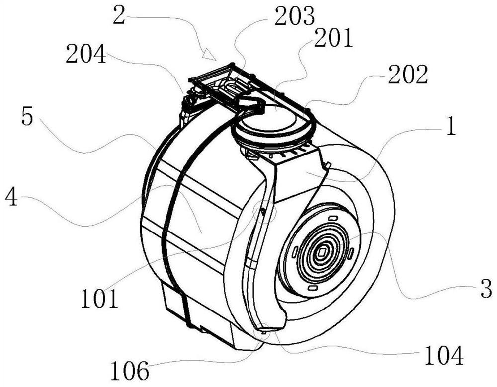
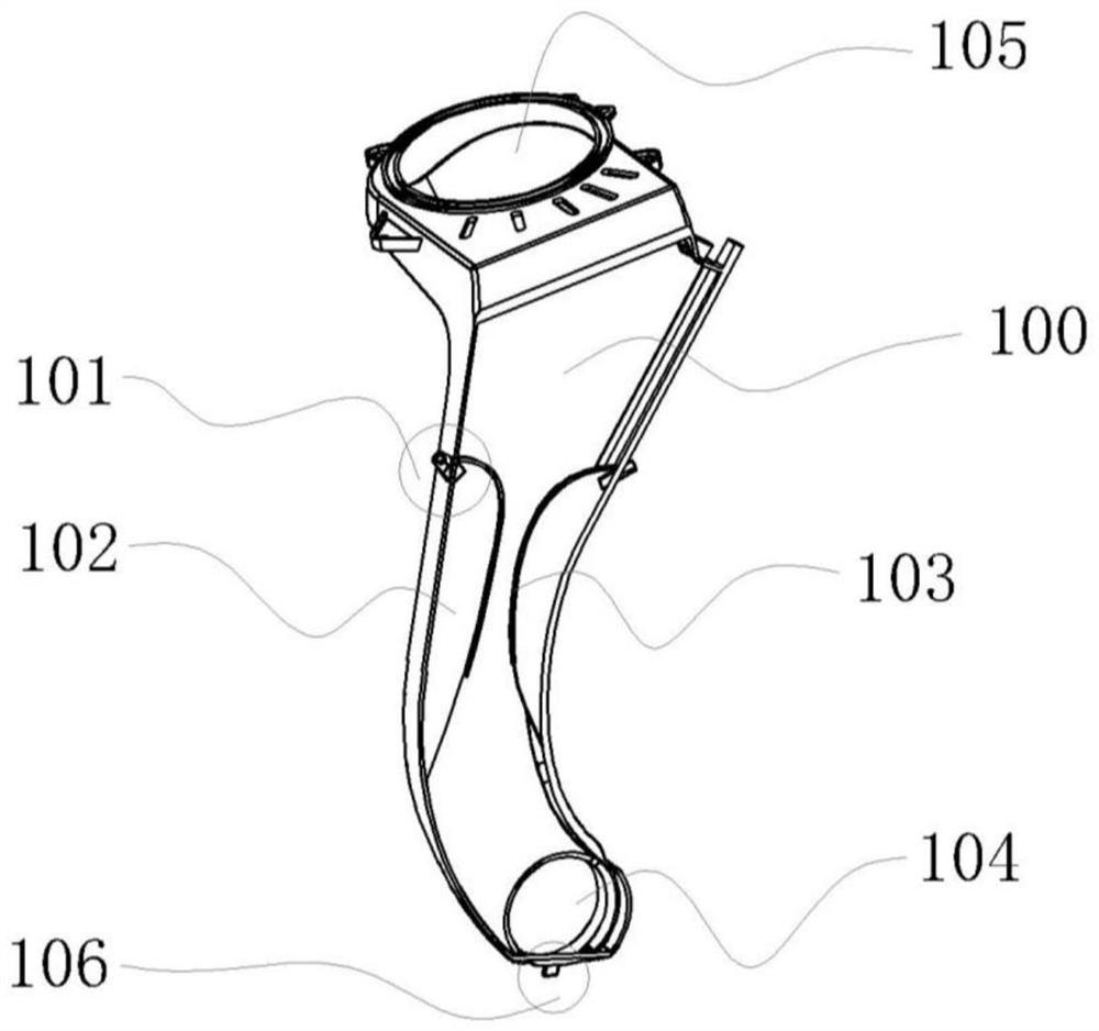
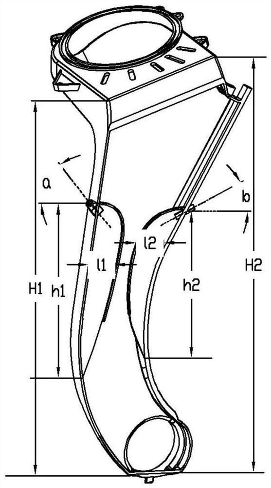

Image

  • A cooling and dehumidifying device
  • A cooling and dehumidifying device
  • A cooling and dehumidifying device

Examples


Embodiment Construction

[0032] Example embodiments will now be described more fully with reference to the accompanying drawings. Example embodiments may, however, be embodied in many forms and should not be construed as limited to the embodiments set forth herein; rather, these embodiments are provided so that this disclosure will be thorough and complete, and will fully convey the concept of example embodiments to those skilled in the art. The same reference numerals denote the same or similar parts in the drawings, and thus their repeated descriptions will be omitted.

[0033] Furthermore, the described features, structures, or characteristics may be combined in any suitable manner in one or more embodiments. In the following description, numerous specific details are provided in order to give a thorough understanding of embodiments of the present disclosure. However, those skilled in the art will appreciate that the technical solutions of the present disclosure may be practiced without one or mo...


PUM


Abstract

The invention provides a cooling and dehumidifying device, which includes a shell, an air inlet, an air outlet, a cooling water inlet joint, a cooling water outlet and a partition plate. The partition plate is arranged in a part of the air duct of the cooling and dehumidification device, and divides the part of the air duct into a direct heat exchange area and an indirect heat exchange area; the cooling water inlet joint sprays cooling water to the partition plate and forms a wall-attached water flow, Scour the partition plate; hot and humid air enters from the bottom of the cooling and dehumidification device, and part of it directly contacts the cooling water in the direct heat exchange area to exchange heat; the other part realizes indirect heat exchange with the cooling water through the partition plate in the indirect heat exchange area. Through the cooling and dehumidification device, the contact area between the cooling water and the hot and humid air is increased without increasing the volume of the heat exchanger, thereby improving the comprehensive condensation heat exchange efficiency.

Description

technical field [0001] The invention relates to the field of heat exchange equipment, in particular to a cooling and dehumidification device. Background technique [0002] In the existing technology and product application market, taking a drum washing machine with a drying function as an example, the drying system mostly adopts a water-cooled heat exchange method, mainly relying on cooling water entering the condenser and exchanging heat with the hot and humid air in the bucket. Cooling water flows in the condenser along one side wall from top to bottom, hot and humid air is sucked into the condenser from bottom to top and exchanges heat with the cooling water. After the air humidity and temperature drop, it returns to the drying air duct to be heated again. Enter the laundry tub to cycle dry. [0003] The cooling water in the condenser in the prior art generally flows in directly from the upper inlet of the condenser, and flows down along the inner wall surface of the con...

Claims


Application Information

Patent Timeline
Patent Type & Authority Patents(China)
IPC IPC(8): D06F58/24
CPCD06F58/24
Inventor 田伶龙斌华刘剑李新稳陈坦
Owner GREE ELECTRIC APPLIANCES INC
Learn More