Pulse jet damping and depressurizing device and using method

A depressurization device and pulse jet technology, applied in drilling equipment and methods, earthwork drilling, drilling with liquid/gas jets, etc., can solve the problems of low efficiency, narrow safe density window, high working cost, etc., to reduce production The effect of reducing costs, saving operating time, and improving service life

Pending Publication Date: 2021-03-26
PETROCHINA CO LTD
View PDF0 Cites 2 Cited by
  • Summary
  • Abstract
  • Description
  • Claims
  • Application Information

AI Technical Summary

Problems solved by technology

[0003] In order to overcome the problems of high working cost and low efficiency caused by the narrow safe density window of the existing deepwater drilling fluid, the present invention provides a pulse jet shock absorbing and pressure reducing device and its use method. The present invention can absorb the mechanical energy generated by the vibration of the drill string, and then Convert mechanical energy into hydraulic energy to provide greater pressure for jet holes, thereby generating greater negative pressure, and finally accelerate the upward return of annular drilling fluid, thereby achieving the purpose of reducing pressure

Method used


Image

  • Pulse jet damping and depressurizing device and using method

Examples


Embodiment 1

[0022] In order to overcome the problems of high working cost and low efficiency caused by the narrow safe density window of the existing deepwater drilling fluid, the present invention provides a pulse jet shock absorbing and pressure reducing device and its use method. The present invention can absorb the mechanical energy generated by the vibration of the drill string, and then The mechanical energy is converted into hydraulic energy to provide greater pressure for the jet hole, thereby generating greater negative pressure, and finally accelerate the upward return of annular drilling fluid, thereby achieving the purpose of reducing pressure. The invention reduces the annular space pressure, prevents the occurrence of leakage, and makes drilling safe and efficient.

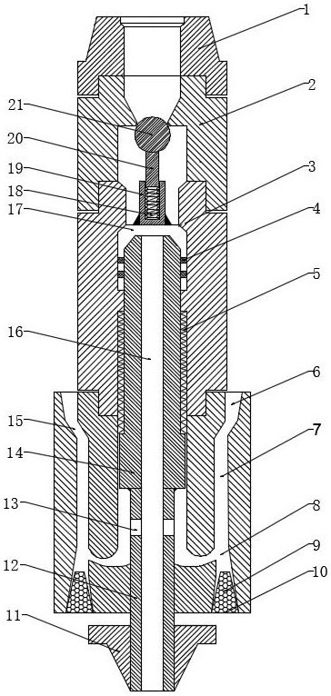
[0023] A pulse jet shock-absorbing and pressure-reducing device, comprising an upper joint 1, an outer cylinder 3, a pressurizing rod 12, a piston 14, a movable sealing device, an injection mechanism and a lower ...

Embodiment 2

[0029] Based on Embodiment 1, in this embodiment, preferably, the lower end of the upper joint 1 and the lower end of the check valve assembly 2 are threaded; the lower joint 11 and the pressure rod 12 are threaded.

[0030]The device is connected to both ends of the drill pipe through a male buckle and a female mouth. The lower end (female thread) of the upper joint 1 is threadedly connected with the upper end (male thread) of the check valve assembly 2 ; the lower joint 11 and the pressure rod 12 are threadedly connected.

[0031] Preferably, the check valve assembly 2 includes a check valve body, a valve seat 19, a spring 18, a valve stem 20 and a valve ball 21, the upper end of the check valve body has a tapered hole, and the check valve The lower end of the body has an inner stepped hole, and the valve ball 21 is located in the inner stepped hole, and the diameter of the valve ball 21 is larger than the minimum inner diameter of the tapered hole; the lower end of the valv...


PUM


Abstract

The invention provides a pulse jet damping and depressurizing device and a using method. The pulse jet damping and depressurizing device comprises an upper connector, an outer barrel, a pressurizing rod, a piston, a movable sealing device, an injection mechanism and a lower connector, a check valve assembly is arranged between the lower end of the upper connector and the upper portion of the outerbarrel, the lower end of the outer barrel is connected with the injection mechanism, the piston is located in the outer barrel, the compression spring is arranged between the piston and the outer barrel, and is positioned at the middle lower portion in the outer barrel; the lower end of the piston is connected with the pressurizing rod, the lower end of the pressurizing rod penetrates through theinjection mechanism and is connected with the lower connector located below the injection mechanism, and the pressurizing rod is connected with the lower portion of the injection mechanism in a sliding and sealing mode; and a jet hole is formed in the upper portion of the pressurizing rod in the radial direction. Vibration of a drill string can be absorbed, absorbed mechanical energy is convertedinto hydraulic injection, the purpose of reducing the bottom hole pressure is finally achieved, and safe and efficient well drilling is guaranteed.

Description

technical field [0001] The invention belongs to the technical field of petroleum drilling, and in particular relates to a pulse jet shock absorbing and pressure reducing device and a using method. Background technique [0002] In deep water drilling, because seawater replaces the rock of land drilling, the pressure of the overlying strata decreases, which reduces the fracture pressure. On the other hand, because the pore pressure in deep water formations is higher than that of land drilling, the formation pressure window is narrow. , in deepwater drilling, the safe drilling fluid density window is very small and difficult to control. If the drilling fluid density is greater than the fracture, then the formation with fractures will be easily lost or fractured. If the drilling fluid density is reduced, but it is lower than the pore pressure, overflow will occur or the well wall will collapse. These complications can lead to increased drilling costs and sometimes even drilling...

Claims


Application Information

Patent Timeline
IPC IPC(8): E21B7/18E21B7/12E21B17/07
CPCE21B7/18E21B7/185E21B7/12E21B17/07
Inventor 段志锋解永刚欧阳勇高云文黄占盈陈春宇艾磊谢江锋宫臣兴张燕娜
Owner PETROCHINA CO LTD
Why Eureka
Try Eureka