
Lighting device based on Internet of Things technology

An Internet of Things technology and lighting device technology, applied in lighting devices, lighting devices, lighting auxiliary devices, etc., can solve the problems of affecting lighting effect and light energy utilization rate, street lamps and solar panels are easy to adhere to dust, etc., to improve the overall utilization rate , Improve the lighting effect and improve the service life of the equipment

Inactive Publication Date: 2021-03-26
陈玉兵
View PDF0 Cites 1 Cited by
  • Summary
  • Abstract
  • Description
  • Claims
  • Application Information

AI Technical Summary

Problems solved by technology

[0004] Aiming at the deficiencies of the prior art, the present invention provides a lighting device based on Internet of Things technology, which solves the problem that street lamps and solar panels are easy to adhere to dust, which affects lighting effects and light energy utilization.

Method used

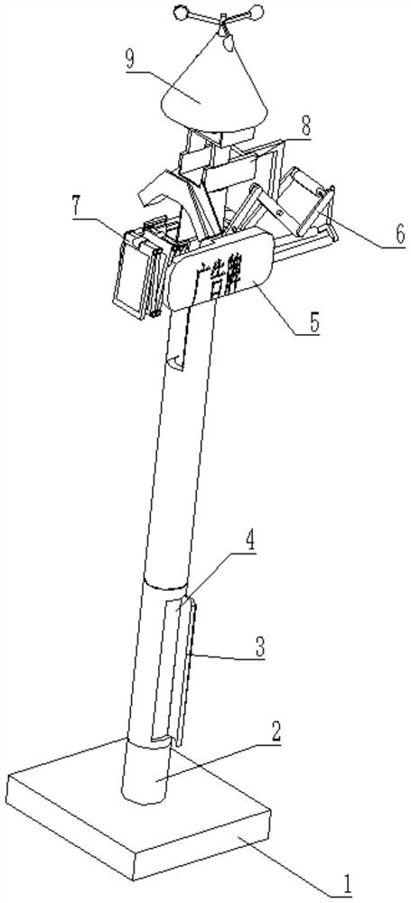

Image

  • Lighting device based on Internet of Things technology
  • Lighting device based on Internet of Things technology
  • Lighting device based on Internet of Things technology

Examples


Embodiment 1

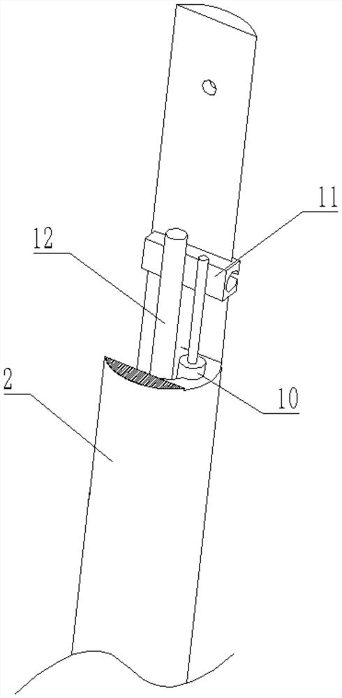
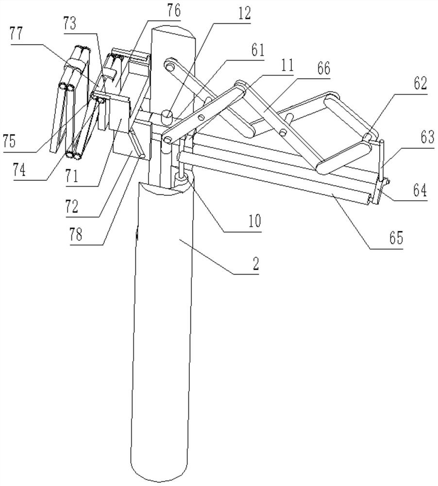
[0030] see Figure 1-4 , a lighting device based on the Internet of Things technology, comprising a mounting base 1, the upper surface of the mounting base 1 is welded with a column 2, the surface of the column 2 is rotatably connected to a flip cover 3, the interior of the column 2 is provided with a battery 4, and the interior of the column 2 The fixed shaft 12 and the electric push rod 10 are fixedly installed respectively, and the electric push rod 10 is located on the right side of the fixed shaft 12, the output end of the electric push rod 10 is provided with an extension mechanism 6, and the surface of the fixed shaft 12 is provided with an extension mechanism 6. The surface of the column 2 is provided with a folding mechanism 7 , the top of the column 2 is provided with a cleaning mechanism 8 , and the top of the cleaning mechanism 8 is provided with a mosquito trap 9 .

[0031] In this embodiment, two advertising boards 5 are fixedly connected to the surface of the up...

Embodiment 2

[0041] see Figure 5-7 On the basis of Embodiment 1, in the present embodiment, the removal mechanism 8 includes a dirt rack 81, the bottom of the dirt rack 81 is fixedly connected to the top of the column 2, and the inner wall of the dirt rack 81 is slidably connected with a push plate 82, and the push plate The right side of 82 is fixedly connected with connecting frame 83, and the bottom of connecting frame 83 is rotatably connected in the inside of telescopic frame 66, and the left side of dirt frame 81 is welded with slide frame 84, and the inside of slide frame 84 offers flow groove 85.

[0042] Through the clearing mechanism 8 provided, the promotion of the connecting frame 83 will be driven during each stretching process of the telescopic frame 66, so that the mosquitoes falling on the inside of the sliding frame 84 will be pushed out and flow out from the position of the flow groove 85 to both sides , to prevent mosquitoes from entering the inside of the folding mecha...


PUM


Abstract

The invention relates to the technical field of lighting, and discloses a lighting device based on the Internet of Things technology, which comprises a mounting base, wherein a stand column is weldedto the upper surface of the mounting base, a flip cover is rotatably connected to the surface of the stand column, a storage battery is arranged in the stand column, and an extending mechanism is arranged at the output end of an electric push rod; an extending mechanism is arranged on the surface of the fixing shaft, a folding mechanism is arranged on the surface of the stand column, a removing mechanism is arranged at the top of the stand column, and a mosquito luring mechanism is arranged at the top of the removing mechanism. According to the lighting device based on the Internet of Things technology, when the lighting device is used in the daytime, the solar panel is unfolded, the lighting lamp is contracted, the lighting lamp is unfolded at night, and the solar panel is folded and contracted, so that dust accumulation can be well avoided, the overall utilization rate is increased, and the lighting device is prevented from being corroded by long-time sun and rain; and therefore, theoverall lighting effect is greatly improved, and the overall service life of equipment is prolonged.

Description

technical field [0001] The invention relates to the technical field of lighting, in particular to a lighting device based on Internet of Things technology. Background technique [0002] At present, with the improvement of the social and economic development level, the urbanization process is accelerating, and the environment of residential quarters is getting better and better. As a part of the living environment of the community, road lighting in the community has attracted more and more attention from the society. At the same time, energy conservation is a socially advocated Part of protecting the environment is also the general direction of social development. [0003] At present, many street lamps will be equipped with solar panels to charge light energy during use, and now many street lamps and solar panels are fixed when they are in use. During the day, the solar panels are used, and at night At night, the street lamps will be used, and at night, the solar panels will...

Claims


Application Information

Patent Timeline
Patent Type & Authority Applications(China)
IPC IPC(8): F21S9/03F21V23/00H02S30/20F21V21/22F21V33/00G09F23/00F21W131/103
CPCF21S9/035F21V21/22F21V23/00F21V33/00F21W2131/103G09F23/00H02S30/20Y02B20/72Y02E10/50
Inventor 陈玉兵
Owner 陈玉兵
Learn More