
Electronic detonator explosion work testing method

An electronic detonator and testing method technology, which is applied in the direction of fuel oil testing, measuring devices, and blasting force measurement, can solve problems such as experiment failure, detonator working ability deviation, volume reading error, etc., and achieve high experimental accuracy and simple operation. Effect

Pending Publication Date: 2021-03-26
ANHUI UNIV OF SCI & TECH
View PDF9 Cites 0 Cited by
  • Summary
  • Abstract
  • Description
  • Claims
  • Application Information

AI Technical Summary

Problems solved by technology

However, this method has some disadvantages. First, the material, size and processing quality of the small lead pots have an essential influence on the experimental results. Small lead pots of different materials and sizes will have different volumes produced by the explosion of the detonator. Therefore, the tested There will be deviations in the working ability of the detonator, so the material and size of the small lead tank must be consistent during the experiment; secondly, the volume readings before and after the explosion of the small lead tank will cause errors and cause inaccurate experimental results; in addition, the temperature reading error will also affect the experiment. It will have an impact, because in the experimental procedure, it is necessary to put the thermometer in the lead hole for 10 minutes before reading the temperature value and correct the detonator’s working ability through the temperature correction coefficient; in addition, the different filling materials and lengths will also affect the experimental results. Influenced, even in the small lead tank experiment, the explosion of the detonator may produce flying pieces, leading to the failure of the experiment

Method used


Image

  • Electronic detonator explosion work testing method
  • Electronic detonator explosion work testing method
  • Electronic detonator explosion work testing method

Examples


Embodiment 1

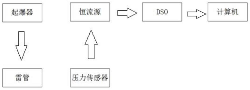
[0049] Fix the electronic detonator and the pressure sensor on a metal rod to keep them on the same horizontal line, and keep a certain distance at the level.

[0050] Put the fixed electronic detonator and pressure sensor into the explosion pool, the depth is 1 / 2 of the depth of the pool, and bind a certain weight of objects under the electronic detonator or the electronic detonator inserted into the charge pack to ensure that it and the pressure sensor are underwater Still level.

[0051] Connect the electronic detonator to the detonating device, the pressure sensor to the constant current source, the DSO and the computer.

[0052] After connecting the device and detonating it, record the data obtained.

[0053] The shock wave energy and bubble energy of the electronic detonator alone are recorded as E1 from the calculated data, and the shock wave energy and bubble energy of the electronic detonator inserted into the charge package are recorded as E2, so the actual working ...


PUM


Abstract

The invention discloses an electronic detonator explosion work testing method. The method comprises the following steps that S1, an explosion module, a pressure testing device and a signal conversiondevice are connected in sequence; S2, two electronic detonators are arranged, so that an annular loop is formed among an explosion device, the first electronic detonator and the signal conversion device; S3, the mass of the explosive package to be exploded is measured; S4, an annular loop among the explosion device, the second electronic detonator, the to-be-exploded charge and the signal conversion device is formed; s5, the explosion device discharges and detonates the first electronic detonator, generated shock waves are transmitted to the signal conversion device through the receiving end,then the second electronic detonator inserted into the to-be-exploded explosive package is detonated, energy released by explosion of the electronic detonator causes explosion of the to-be-exploded explosive package, and then explosion shock waves generated by the first electronic detonator and the second electronic detonator are transmitted to the signal conversion device; S6, the P-t curves recorded for the first time and the second time are respectively recorded as P1 and P2; and S7, shock wave energy and bubble energy are calculated. The method is accurate in experimental result and simpleand convenient to operate.

Description

technical field [0001] The invention relates to the field of practical application of electronic detonators, in particular to a method for testing electronic detonator explosion work. Background technique [0002] Digital electronic detonator is a detonating device that uses an electronic chip control module to achieve precise delay. In recent years, due to the increasingly urgent demand for safety control of the use of civil explosives in my country, digital electronic detonators perfectly meet my country's urgent control requirements for civil explosives. Therefore, under the vigorous promotion of the country, the digital electronic detonator has developed rapidly in China, and the digital electronic detonator technology has been continuously developed and improved. Its technical superiority has been more and more widely recognized in the blasting industry. More and more common, expanding from the early field of rare and precious mineral mining to ordinary mines and quarr...

Claims


Application Information

Patent Timeline
Patent Type & Authority Applications(China)
IPC IPC(8): G01N33/22G01L5/14F42C21/00
CPCG01N33/227G01L5/14F42C21/00
Inventor 何志伟汪扬文孟涛朱文宇李远园刘锋郭子如
Owner ANHUI UNIV OF SCI & TECH
Learn More