Voltage stabilizing device for glue coating and developing equipment and glue coating and developing equipment

A technology of glue developing and voltage stabilization device, which is applied in the fields of optomechanical equipment, microlithography exposure equipment, photolithography process exposure device, etc. Longer service life, reduced rework rate, stable uniformity effect

Active Publication Date: 2022-06-03
SHANGHAI HUALI MICROELECTRONICS CORP
View PDF6 Cites 1 Cited by
  • Summary
  • Abstract
  • Description
  • Claims
  • Application Information

AI Technical Summary

Problems solved by technology

But when the external air pressure is affected by bad weather (such as typhoon), the external air pressure decreases rapidly, and the object stage chamber 10 and the interaction chamber 50 communicated with the outside world are first affected, because only dust-proof The circulating gas filter 80, a large amount of air leakage in the stage chamber 10 and the interaction chamber 50 cause the air pressure in the wafer transfer chamber 20 and the cleaning chamber 40 to also decrease rapidly, and finally pass to the glue-coating and developing chamber 30, and the coating The glue developing chamber 30 is deflated a lot, and the outward exhaust air flow W4 of the glue developing chamber 30 also drops rapidly simultaneously, resulting in the decrease of the exhaust air flow W1 entering the spin coating chamber 70, and the film with high flatness on the wafer surface Due to the fluctuation of the exhaust air flow W1, the jagged feature of the film surface is enlarged, that is, the range of the film thickness (range) becomes larger, that is, the uniformity of the film thickness is reduced, and it often exceeds the specification (Spec, within a certain range above and below the target value, this The range is determined by the specific process)
[0005] Therefore, it is necessary to propose a voltage stabilizing device for glue coating and developing equipment to solve the problem that the film thickness jump on the wafer surface exceeds the specification caused by the violent fluctuation of the external atmospheric pressure of the equipment

Method used


Image

  • Voltage stabilizing device for glue coating and developing equipment and glue coating and developing equipment
  • Voltage stabilizing device for glue coating and developing equipment and glue coating and developing equipment
  • Voltage stabilizing device for glue coating and developing equipment and glue coating and developing equipment

Examples


Embodiment Construction

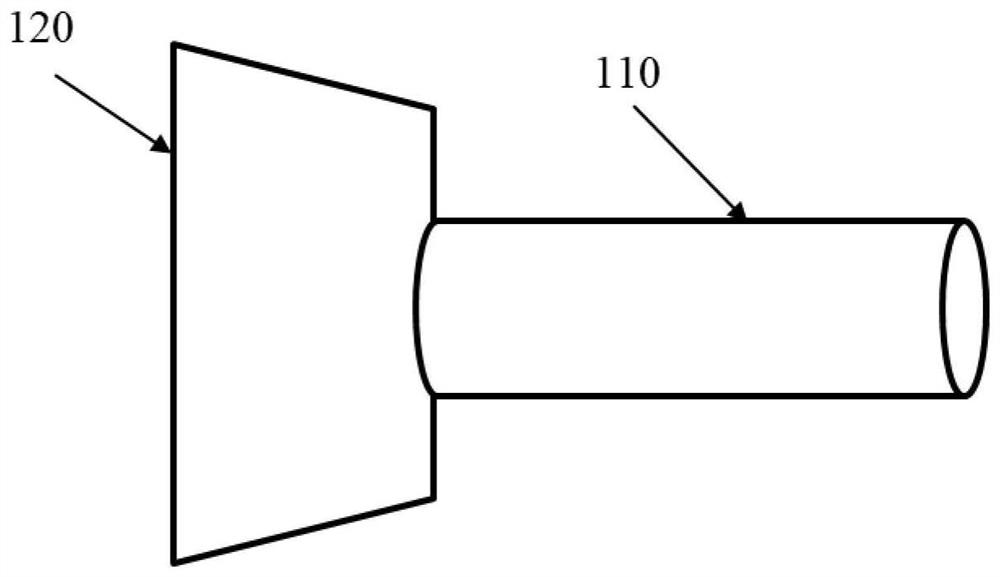
[0047] The diversion port 120 is disposed at the air inlet end 131 of the wind tunnel 110, and communicates with the through hole 130. the guide

[0049] The limiting port 114 is disposed on the side wall of the through hole 130 close to the air inlet end 131 (ie the wind tunnel).

[0050] The piston 112 is located on the side of the limiting port 114 close to the air inlet end 131, and the piston 112 and

[0051] The spring 116 is arranged on the side of the limiting port 114 away from the air inlet end 131, and the spring 116 is ring-shaped.

[0052] The crank 117 and the crank connecting rod 118 are arranged on a side of the spring 116 away from the air inlet end 131.

[0053] When the piston 112 is in contact with the limit opening 114 (ie, the through hole 130 is closed), the spring 116 is in the

[0054] The propeller 113 is arranged at one end of the bearing 111 close to the air outlet end 132, and the propeller

[0057] In a stable state, the crank 117 and the bearing 111 a...


PUM


Abstract

The present invention provides a voltage stabilizing device for glue-coating and developing equipment and the glue-coating and developing equipment. The voltage stabilizing device for glue-coating and developing equipment includes a wind tunnel, which has an air inlet end and an air outlet that axially penetrate both ends of the wind tunnel. The through hole at the air end, the side wall of the through hole is provided with a limit opening; the bearing is axially arranged in the through hole; the piston cooperates with the limit opening to open or close the through hole; the spring, the spring One end close to the limit port is fixed on the bearing through a spring limit rod on the bearing; the crank and crank connecting rod are arranged on the side of the spring far away from the air inlet end, and the The crank is connected to the end of the spring far away from the limiting opening; the propeller is arranged on the end of the bearing close to the air outlet. The technical solution provided by the invention can stabilize the pressure difference between the glue application developing chamber and the outside atmosphere, thereby enabling the uniformity of the film thickness on the surface of the wafer to be controlled within the specification and reducing the rework rate of the wafer.

Description

The voltage stabilizer of the glue coating and developing equipment and the glue coating and developing equipment technical field The present invention relates to the field of semiconductor manufacturing, in particular to a voltage stabilizer of a glue-coating developing device and a glue-coating display device. shadow equipment. Background technique In the process of manufacturing semiconductor devices, the equipment used in the photolithography process includes a glue developing equipment (Track equipment). equipment) and exposure equipment. Among them, the glue coating and developing equipment contains many work areas with different functions, and each work area is a single work area. Separate chambers, the chambers in each working area communicate with each other and communicate with the exposure chambers in the exposure equipment. Referring to Fig. 1, Fig. 1 is the structural representation of existing glue developing equipment, as can be seen from Fig. 1, glue...

Claims


Application Information

Patent Timeline
Patent Type & Authority Patents(China)
IPC IPC(8): G03F7/20
CPCG03F7/70858G03F7/70808
Inventor 陈力钧吴国光莫少文
Owner SHANGHAI HUALI MICROELECTRONICS CORP
Why Eureka
Try Eureka