
Reference current source and chip comprising reference current source

A reference current source and resistance technology, applied in the direction of adjusting electrical variables, control/regulating systems, instruments, etc., can solve the problems of low accuracy, high temperature drift, complicated circuit lines, etc., to improve accuracy, reduce complexity and temperature. The effect of drifting and eliminating non-ideal factors

Inactive Publication Date: 2021-03-26
SHANGHAI BEILING
View PDF8 Cites 1 Cited by
  • Summary
  • Abstract
  • Description
  • Claims
  • Application Information

AI Technical Summary

Problems solved by technology

[0003] The technical problem to be solved by the present invention is to provide a reference current source and a chip containing the reference current source in order to overcome the defects of complex circuit lines, high temperature drift and low precision caused by the use of external operational amplifiers in the prior art

Method used


Image

  • Reference current source and chip comprising reference current source
  • Reference current source and chip comprising reference current source

Examples


Embodiment 1

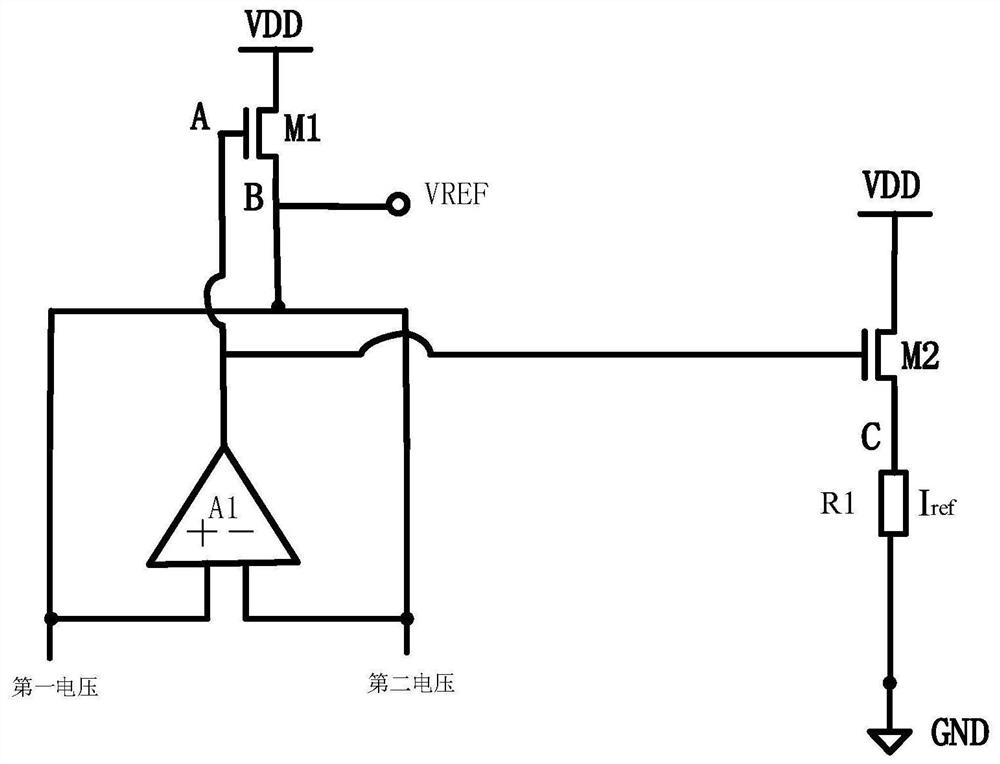
[0038] This embodiment provides a reference current source, such as figure 1 As shown, it includes a first transistor M1, a second transistor M2, an operational amplifier A1 and a first resistor R1.

[0039] The non-inverting input terminal + and the inverting input terminal - of the operational amplifier A1 are respectively connected to the first voltage and the second voltage, the first voltage and the second voltage are equal, and the output terminal of the operational amplifier A1 is respectively connected to the gate of the first transistor M1 and The gate of the second transistor M2 is electrically connected.

[0040] Both the drains of the first transistor M1 and the second transistor M2 are connected to the external power supply VDD, the sources of the first transistor M1 are electrically connected to the non-inverting input terminal + of the operational amplifier A1 and the inverting input terminal - of the operational amplifier A1 respectively, and the second The so...

Embodiment 2

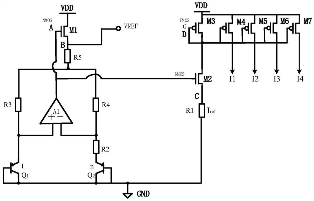
[0053] A reference current source provided in this embodiment is further improved on the reference of Embodiment 1, such as figure 2 As shown, both the first transistor M1 and the second transistor M2 are NMOS transistors.

[0054] The reference current source in this embodiment also includes a first triode Q1 and a second triode Q2, the bases and collectors of the first triode Q1 and the second triode Q2 are grounded to GND, and the first triode The emitter of the transistor Q1 is electrically connected to the non-inverting input terminal + of the operational amplifier A1 for generating the first voltage, and the emitter of the second transistor Q2 is electrically connected to the inverting input terminal - of the operational amplifier A1 for generating the first voltage Second voltage. In this embodiment, the first triode Q1 and the second triode Q2 respectively generate equal first voltage and second voltage.

[0055] In another optional implementation manner, the refere...

Embodiment 3

[0067] The chip of this embodiment includes the reference current source of Embodiment 1 or 2, and the reference current source is used to provide reference currents to various circuit parts in the chip.

[0068] The performance of the chip in this embodiment is more stable by using the above-mentioned reference current source circuit.


PUM


Abstract

The invention discloses a reference current source and a chip comprising the reference current source. The reference current source comprises a first transistor, a second transistor, an operational amplifier and a first resistor. A first voltage and a second voltage are respectively connected to the in-phase input end and the anti-phase input end of the operational amplifier, the first voltage isequal to the second voltage, and the output end of the operational amplifier is electrically connected with the grid electrode of the first transistor and the grid electrode of the second transistor respectively; drain electrodes of the first transistor and the second transistor are connected with an external power supply; the source electrode of the first transistor is electrically connected withthe in-phase input end and the anti-phase input end respectively; the source of the second transistor is connected with one end of the first resistor, and the other end of the first resistor is grounded. A reference current is generated through the first transistor, the operational amplifier, the second transistor and the first resistor, an external operational amplifier is omitted, non-ideal factors of the external operational amplifier are eliminated, the complexity and temperature drift of a reference current source circuit are reduced, and the accuracy of a reference current source is improved.

Description

technical field [0001] The invention relates to the technical field of integrated circuits, in particular to a reference current source and a chip containing the reference current source. Background technique [0002] The reference current source is an indispensable unit in the chip. With the application of the chip and the change of the environment, the chip has higher and higher requirements on the reference current source. The existing reference current source is realized by using a reference voltage source to generate a reference voltage, and then using an external operational amplifier and a transistor to form a source follower, and using a resistor to generate a reference current. Due to the offset and noise problems of the operational amplifier, the stability of the source follower composed of the operational amplifier and the transistor is poor, and the reference current implementation circuit is complex, with high temperature drift and low precision. Contents of t...

Claims


Application Information

Patent Timeline
IPC IPC(8): G05F1/56
CPCG05F1/56
Inventor 袁文师
Owner SHANGHAI BEILING
Learn More