Cable branch box processing method
A technology of cable branch box and processing method, which is applied in the direction of cable joints, electrical components, electromagnetic audible signals, etc., can solve the problems of poor protection effect, etc., and achieve the effects of strong practicability, good self-protection function, and high degree of automation
- Summary
- Abstract
- Description
- Claims
- Application Information
AI Technical Summary
Problems solved by technology
Method used
Image
Examples
Embodiment 1
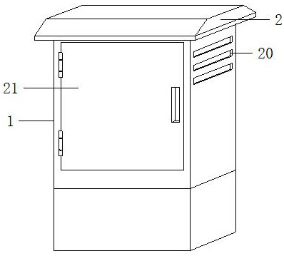
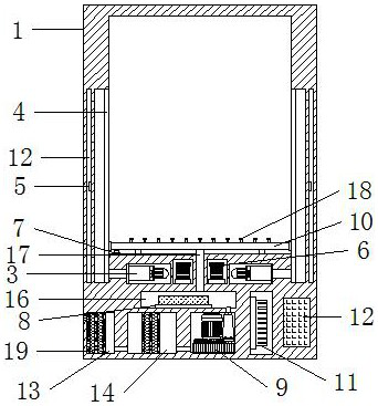
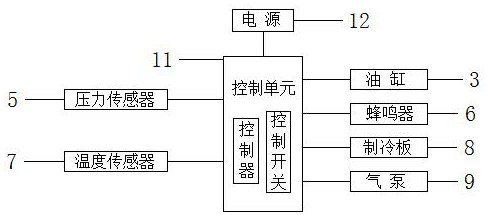
[0027] It includes a box body 1 and a top cover 2. The top cover 2 is welded on the top of the box body 1. There is an inner cavity in the box body 1. An automatic protection structure and a temperature control structure are arranged in the box body 1. The automatic protection structure includes an oil cylinder 3, a protection Board 4, pressure sensor 5 and buzzer 6, control unit 11 and power supply are arranged in box body 1, control unit 11 and power supply are respectively connected with control unit 11 through wires, control unit 11 is respectively connected with oil cylinder 3, buzzer through wires The device 6, the refrigeration plate 8 and the air pump 9 are connected, grooves are arranged on both sides of the inner wall of the inner cavity, and a detection chamber 12 is arranged inside the inner wall of the groove, the pressure sensor 5 is installed in the detection chamber 12, and the protection plate 4 is clamped on the In the groove, the bottom of the inner cavity is...
Embodiment 2
[0030] It includes a box body 1 and a top cover 2, the top cover 2 is welded on the top of the box body 1, an inner cavity is arranged in the box body 1, an automatic protection structure and a temperature control structure are arranged in the box body 1, and the temperature control structure includes a temperature sensor 7, Refrigeration plate 8, air pump 9 and discharge pipe 10, control unit 11 and power supply are arranged in box body 1, control unit 11 and power supply are respectively connected with control unit 11 through wires, control unit 11 is connected with oil cylinder 3, buzzer respectively through wires 6. The refrigeration plate 8 is connected to the air pump 9, grooves are provided on both sides of the inner wall of the inner cavity, and a detection chamber 12 is arranged inside the inner wall of the groove, the pressure sensor 5 is installed in the detection chamber 12, and the protection plate 4 is stuck in the concave In the groove, the bottom of the inner ca...
PUM
 Abstract
Description
Claims
Application Information
 - R&D
- Intellectual Property
- Life Sciences
- Materials
- Tech Scout
- Unparalleled Data Quality
- Higher Quality Content
- 60% Fewer Hallucinations
Browse by: Latest US Patents, China's latest patents, Technical Efficacy Thesaurus, Application Domain, Technology Topic, Popular Technical Reports.
© 2025 PatSnap. All rights reserved.Legal|Privacy policy|Modern Slavery Act Transparency Statement|Sitemap|About US| Contact US: help@patsnap.com


