
Novel quick-response direct-current current limiter and current limiting method

A fast-response, current limiter technology, which is applied in the direction of emergency protection circuit devices, electrical components, emergency protection circuit devices, etc. for limiting overcurrent/overvoltage, can solve the problem of limiting the rising speed of short-circuit current and large overvoltage of circuit breakers And energy absorption, increase the manufacturing cost of circuit breakers and other issues, to achieve the effect of reducing overvoltage, eliminating negative effects, and reducing energy absorption

Inactive Publication Date: 2021-03-26
WUHAN UNIV
View PDF5 Cites 2 Cited by
  • Summary
  • Abstract
  • Description
  • Claims
  • Application Information

AI Technical Summary

Problems solved by technology

When a short-circuit fault occurs, the magnetic flux generated by the large current is sufficient to offset the magnetic flux of the permanent magnet, the iron core is out of saturation, and high inductance is rapidly generated in the DC coil, thereby limiting the rising speed of the short-circuit current
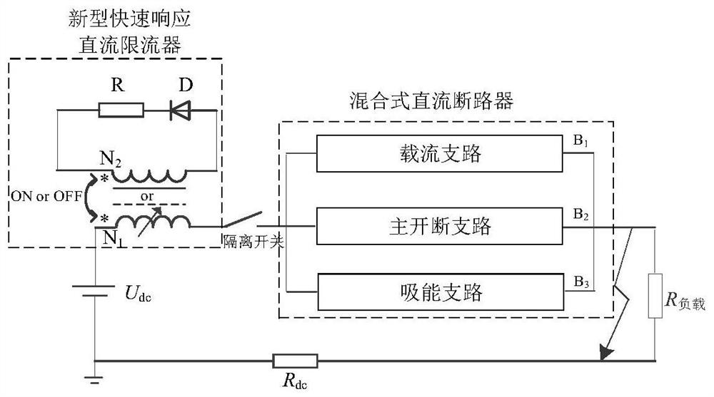
However, when the existing traditional magnetically saturated core-type DC fault current limiter is used with a DC circuit breaker, it will cause the circuit breaker to withstand a large overvoltage and absorb energy, which increases the manufacturing cost of the circuit breaker.
And seriously suppress the fault current drop rate, prolong the time for the fault current to act on the power system, and cause damage to related power equipment

Method used


Image

  • Novel quick-response direct-current current limiter and current limiting method
  • Novel quick-response direct-current current limiter and current limiting method
  • Novel quick-response direct-current current limiter and current limiting method

Examples


Embodiment

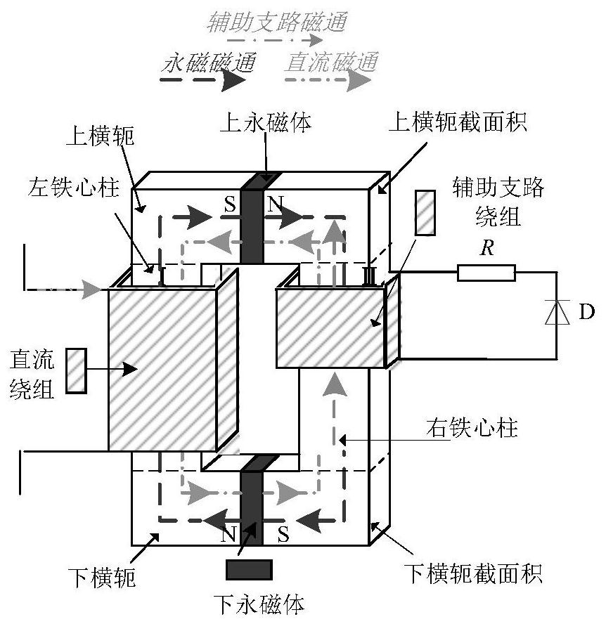
[0028] like figure 2 As shown, a new type of fast-response DC current limiter, the current limiter includes an iron core, a DC winding and a permanent magnet; , which are respectively located at the upper and lower yokes at the upper and lower ends. A first permanent magnet is embedded in the middle of the upper yoke, and a second permanent magnet is embedded in the middle of the lower yoke. The main branch winding is wound on the left core leg and connected to the DC power grid in series, and the auxiliary branch winding is wound on the right core leg. When the current limiter is connected to the transmission line for operation, the DC magnetic flux forms a loop through the iron core, and the magnetic flux generated by the excitation of the permanent magnet also forms a loop in the iron core, and the two magnetic fluxes act together on the entire iron core column.

[0029] The peripheral circuit of the auxiliary branch includes a diode D and an energy-absorbing resistor R,...


PUM


Abstract

The invention relates to a novel quick-response direct-current current limiter and a current limiting method. Through additionally arranging an auxiliary branch circuit to a right iron core column ofa traditional two-column saturated iron core type direct-current current limiter, the negative effect of prolonging the fault current drop time of an original current limiter when a direct-current circuit breaker fails and is broken is eliminated, the breaking process is accelerated, the energy absorption stress of the circuit breaker is reduced, the overvoltage stress is reduced, the response speed is accelerated, and the insulation cost is reduced.

Description

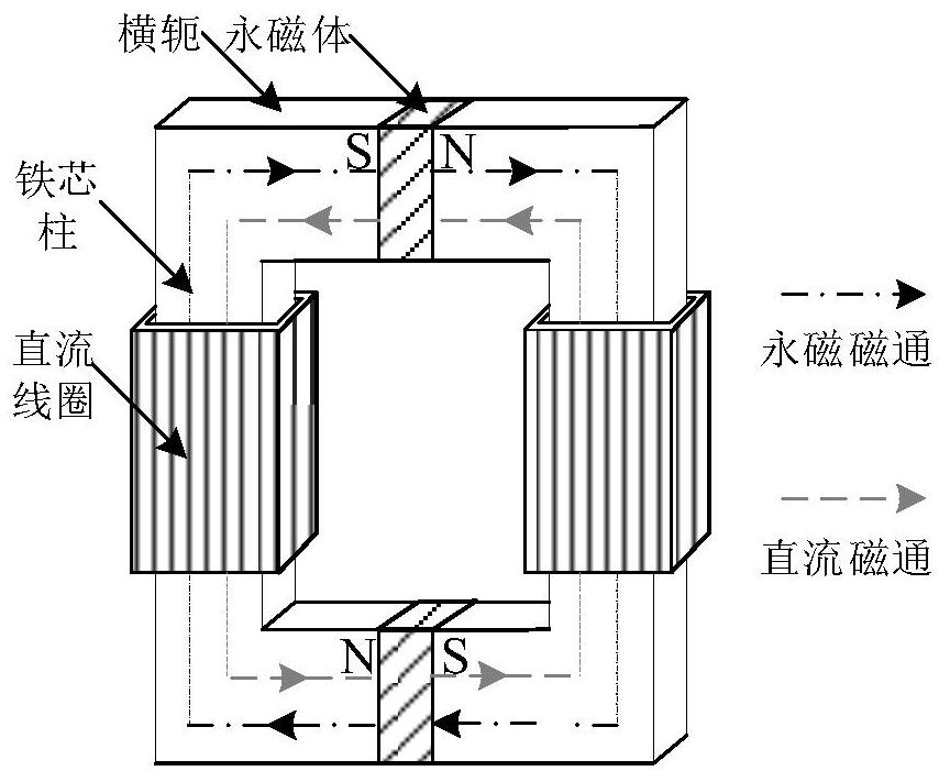
technical field [0001] The invention relates to a magnetically saturated iron core type DC fault current limiter and a current limiting method, in particular to a novel fast-response DC current limiter and a current limiting method. Background technique [0002] The rapid rise of the fault current in the HVDC system has been threatening the safe operation of the HVDC system. Therefore, a fault current limiter that limits the rising speed of the fault current is essential for the safe operation of the system. The structure diagram of the existing traditional magnetic saturation type DC fault current limiter is as follows: figure 1 , A variable inductance is generated by embedding a permanent magnet in the iron core. The magnetic field direction of the permanent magnet is opposite to the magnetic field direction generated by the DC current in the coil. The magnetic field of the permanent magnet makes the iron core in a magnetic saturation state. When working normally, the mag...

Claims


Application Information

Patent Timeline
Patent Type & Authority Applications(China)
IPC IPC(8): H02H9/02
CPCH02H9/021
Inventor 袁佳歆陈鹤冲周航叶丛韬
Owner WUHAN UNIV
Learn More