
Magnetic levitation motor protection structure, magnetic levitation system and turbomachine

A protection structure and magnetic levitation technology, applied in the direction of magnetic circuit shape/style/structure, control mechanical energy, electrical components, etc., can solve problems such as rotor jamming, rotor damage, shrinkage, etc., and achieve simple protection structure, high overall reliability, The effect of preventing the rotor from getting stuck

Pending Publication Date: 2021-03-26
SUZHOU SUPERMAG INTELLIGENT TECH CO LTD
View PDF0 Cites 0 Cited by
  • Summary
  • Abstract
  • Description
  • Claims
  • Application Information

AI Technical Summary

Problems solved by technology

However, when the working temperature is high, due to the thermal expansion and contraction characteristics of the material, the rotor will elongate in the axial direction, thereby squeezing the limit parts at both ends, resulting in the limit parts at both ends being squeezed and in contact with the protective bearing. The axial gap will be reduced until the gap between the limit parts and the protective bearings at both ends is 0, the rotor will be locked by the limit parts in the axial direction and stop rotating, and further, the rotor will be damaged
The above problems will cause the magnetic levitation motor to be unusable
[0006] In view of the above problems, if the motor cooling system is added on the basis of the existing scheme, although the influence caused by the rise of the working temperature can be reduced to a certain extent, the cooling system will increase the design complexity of the magnetic levitation motor, and will cause the magnetic levitation motor When the working temperature is high, it completely depends on the reliability of the cooling system, which reduces the stability of the magnetic levitation motor
[0007] To sum up, the field needs to improve the protection structure of the magnetic levitation motor to solve the problem of rotor stuck when the working temperature is high

Method used


Image

  • Magnetic levitation motor protection structure, magnetic levitation system and turbomachine
  • Magnetic levitation motor protection structure, magnetic levitation system and turbomachine
  • Magnetic levitation motor protection structure, magnetic levitation system and turbomachine

Examples


Embodiment Construction

[0035] The following will clearly and completely describe the technical solutions in the embodiments of the present invention with reference to the accompanying drawings in the embodiments of the present invention. Obviously, the described embodiments are only some, not all, embodiments of the present invention. Based on the embodiments of the present invention, all other embodiments obtained by persons of ordinary skill in the art without making creative efforts belong to the protection scope of the present invention.

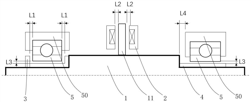
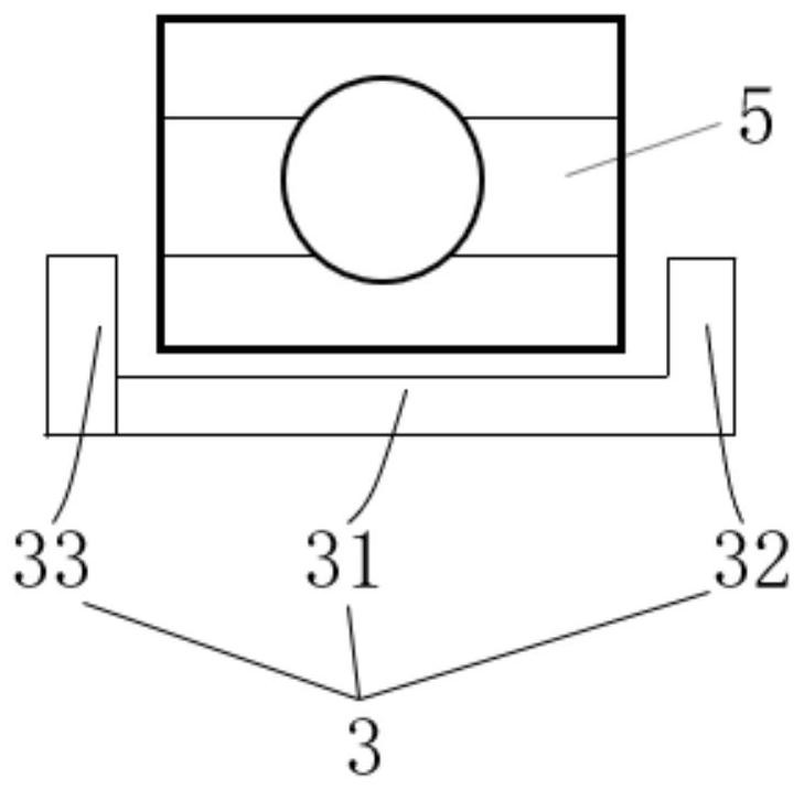
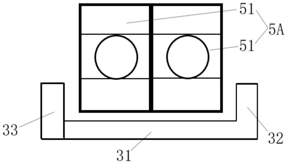
[0036] Such as figure 1 Shown is a first preferred embodiment of a protection structure for a magnetic levitation motor according to the present invention. The protection structure for a magnetic levitation motor includes a rotor 1 , an axial and radial limit assembly 3 and a radial limit assembly 4 . An axial magnetic bearing assembly is arranged on the side of the rotor 1 , and the axial magnetic bearing assembly includes an axial magnetic bearing 2 and a th...


PUM


Abstract

The invention discloses a protection structure of a magnetic levitation motor. The protection structure comprises a rotor, an axial and radial limiting assembly, a radial limiting assembly and a protection bearing, the axial and radial limiting assembly and the radial limiting assembly are located at the two ends of the rotor correspondingly, the axial and radial limiting assembly and the radial limiting assembly are arranged to be aligned with the at least one protective bearing correspondingly, and the axial and radial limiting assembly and the radial limiting assembly rotate synchronously with the rotor. The protection structure of the magnetic levitation motor can effectively prevent the rotor from being stuck at a high working temperature.

Description

technical field [0001] The invention relates to the technical field related to magnetic levitation motors, and more precisely relates to a protective structure of a magnetic levitation motor, a magnetic levitation system and a turbomachinery. Background technique [0002] The stator and rotor of traditional motors are connected by mechanical bearings or have mechanical contact. When the rotor moves, there is mechanical friction between the stator and the rotor. Mechanical friction will increase the friction resistance of the rotor, cause wear of moving parts, generate mechanical vibration and noise, and cause heating of motor components, which will reduce the performance of the lubricant in it. In severe cases, it will reduce the uniformity of the motor air gap and make the winding Heat generation, temperature rise increases, resulting in reduced performance of the motor, and will shorten the service life of the motor. [0003] The magnetic levitation motor uses the princip...

Claims


Application Information

Patent Timeline
Patent Type & Authority Applications(China)
IPC IPC(8): H02K7/09H02K1/22H02K1/12
CPCH02K1/12H02K1/22H02K7/09
Inventor 尹成科吴文志尤志强
Owner SUZHOU SUPERMAG INTELLIGENT TECH CO LTD
Learn More