Multi-level converter topology suitable for medium and high voltage occasions and control method

A control method and multi-level technology, applied in the direction of adjusting electrical variables, control/regulation systems, output power conversion devices, etc., can solve the problem of unsatisfactory working characteristics and voltage of high-voltage devices, high price, and insufficient voltage boost of a single module Waiting for questions

Inactive Publication Date: 2021-03-26
NR ELECTRIC CO LTD +1
View PDF5 Cites 7 Cited by
  • Summary
  • Abstract
  • Description
  • Claims
  • Application Information

AI Technical Summary

Problems solved by technology

[0004] There are relevant researches at home and abroad on high-voltage semiconductor power devices to improve the working voltage level of single power modules. However, due to the development process of semiconductor power devices, the working characteristics and voltage of high-voltage devices are still not ideal, and the price is expensive. Medium and low voltage semiconductor power devices are still Is the mainstream application
Some research units proposed to increase the operating voltage level of a single module through multi-level topology, such as CN110768534A, which proposed a three-level circuit structure. Under the same withstand voltage device conditions, the operating voltage was doubled, but for a single module The voltage increase is not much; or a five-level inverter circuit topology (CN201520371204.6) is proposed, but the working voltage level of a single module is not improved

Method used


Image

  • Multi-level converter topology suitable for medium and high voltage occasions and control method
  • Multi-level converter topology suitable for medium and high voltage occasions and control method
  • Multi-level converter topology suitable for medium and high voltage occasions and control method

Examples


Embodiment Construction

[0068] The implementation of the technical solution will be further described in detail below in conjunction with the accompanying drawings.

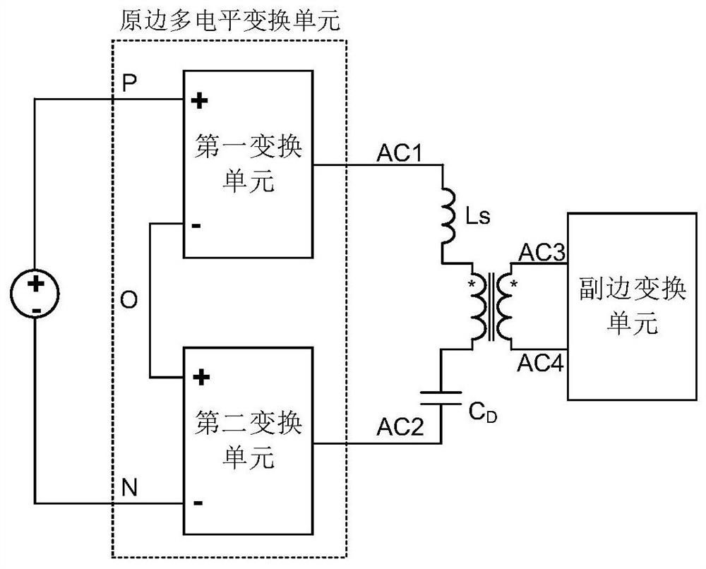
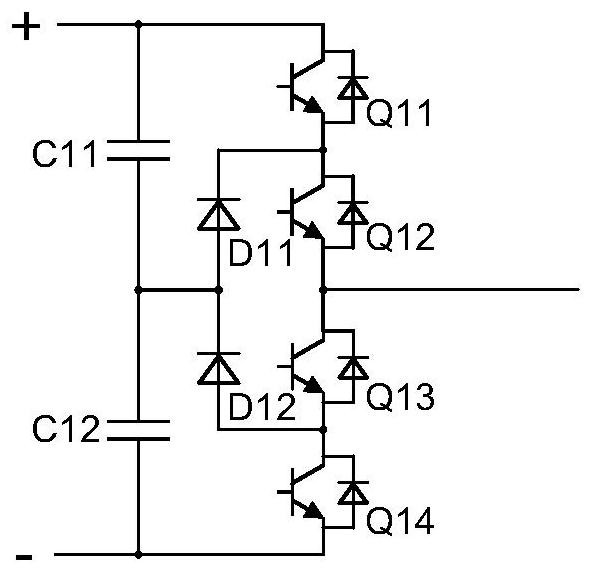
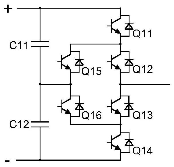
[0069] as attached figure 1 As shown, a schematic diagram of a multilevel converter topology suitable for medium and high voltage applications proposed by the present invention, the multilevel converter topology consists of a first DC blocking capacitor C D , the first phase-shifting inductance L S , a first isolation transformer, a primary-side multi-level conversion unit and a secondary-side conversion unit. The secondary conversion unit is used to convert AC power into DC power. The primary-side multilevel conversion unit is composed of a first conversion unit and a second conversion unit connected in series; the first conversion unit and the second conversion unit are used to convert direct current into alternating current; the first conversion unit and the second conversion unit The conversion units are all clamped half-bridge t...


PUM


Abstract

The invention discloses a multi-level converter topology suitable for a medium-high voltage occasion and a control method. The multi-level converter topology is composed of a first blocking capacitor,a first phase-shifting inductor, a first isolation transformer, a primary side multi-level conversion unit and a secondary side conversion unit. The primary side multi-level conversion unit is formedby connecting a first conversion unit and a second conversion unit in series. The alternating-current output end of the first conversion unit and the alternating-current output end of the second conversion unit are connected with the first blocking capacitor, the first phase-shifting inductor and the primary side of the first isolation transformer in series to form the primary side of the multilevel converter. On the premise of the same power device, the series structure of the two conversion units greatly improves the working voltage level of a single module, and reduces the size and cost ofthe system. By adopting the control method provided by the invention, the transformer current under the condition that the input and output voltages are not matched is reduced, the converter loss isreduced, and DC voltage balance of the first conversion unit and the second conversion unit is maintained.

Description

technical field [0001] The invention relates to the field of high-voltage electric energy conversion in a power system, in particular to the application of a power electronic transformer. Background technique [0002] Taking the power electronic transformer in the application of smart distribution network as an example, compared with the traditional industrial frequency transformer, it has the advantages of bidirectional power flow control, power quality management, fault isolation, direct access to new energy DC, and does not require oil cooling. , There is a tendency to gradually replace power frequency transformers in power systems. [0003] However, in order to meet the requirements of high-voltage access, the high-voltage side is a topology of modules connected in series. At present, power electronic transformers have many modules connected in series and the equipment is bulky, which limits the application and promotion of power electronic transformers. How to reduce t...

Claims


Application Information

Patent Timeline
Patent Type & Authority Applications(China)
IPC IPC(8): H02M7/483H02M7/5395H02M7/5387H02M3/335
CPCH02M3/3353H02M7/483H02M7/53871H02M7/5395
Inventor 汪涛文继锋骆仁松虞晓阳张茂强李响
Owner NR ELECTRIC CO LTD
Why Eureka
Try Eureka