
Vehicle transaxle assembly

A technology for drive axles and components, which is applied to vehicle components, transmission components, vehicle gearboxes, etc. It can solve the problems of easy cracking and strain on the joint surface, small ground clearance of the vehicle, and oil leakage, so as to reduce the loss of oil churning power, The effect of reducing working noise and improving transmission efficiency

Active Publication Date: 2022-08-09
BYD CO LTD
View PDF6 Cites 0 Cited by
  • Summary
  • Abstract
  • Description
  • Claims
  • Application Information

AI Technical Summary

Problems solved by technology

[0002] In the related art, the structure of the drive axle assembly of the vehicle is complicated, and the finished product is expensive; When the car is running, a large torque will be generated on the bonding surface of the bridge assembly and the power assembly, and the bonding surface is prone to cracking or large strain, resulting in oil leakage
At the same time, the gear shifting method of the existing drive axle components is electro-hydraulic module shifting, and the entire module structure is complicated, expensive, and maintenance costs are high
When the drive axle assembly transmits torque, each gear is in working condition, there is no idle gear, the service life of the gear is short and the noise of the whole assembly is relatively large
[0003] In addition, the height of some shafts and gear centers in the drive axle assembly is lower than the height of the differential. After the drive axle assembly is installed on the vehicle, the shafts and gears are completely immersed in gear oil. When the powertrain of the drive axle assembly When working, the gear on the shaft throws oil at high speed, which easily leads to relatively high oil temperature of the entire powertrain, which in turn leads to component failure

Method used


Image

  • Vehicle transaxle assembly
  • Vehicle transaxle assembly
  • Vehicle transaxle assembly

Examples


Embodiment Construction

[0048] The following describes in detail the embodiments of the present invention, examples of which are illustrated in the accompanying drawings, wherein the same or similar reference numerals refer to the same or similar elements or elements having the same or similar functions throughout. The embodiments described below with reference to the accompanying drawings are exemplary, only used to explain the present invention, and should not be construed as a limitation of the present invention.

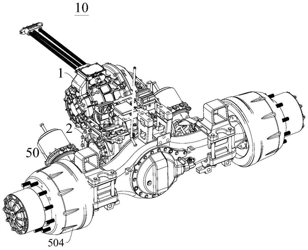
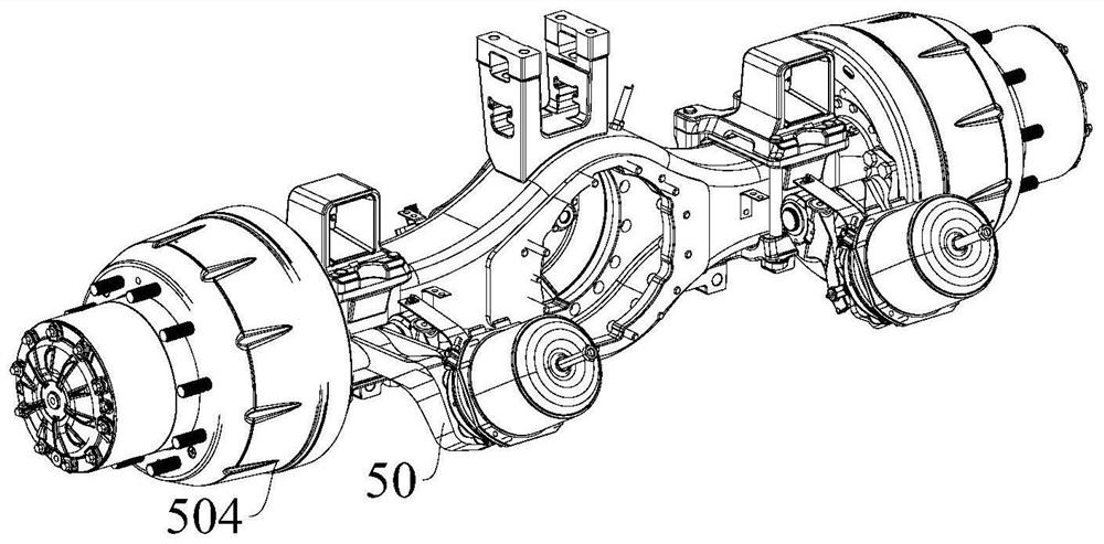
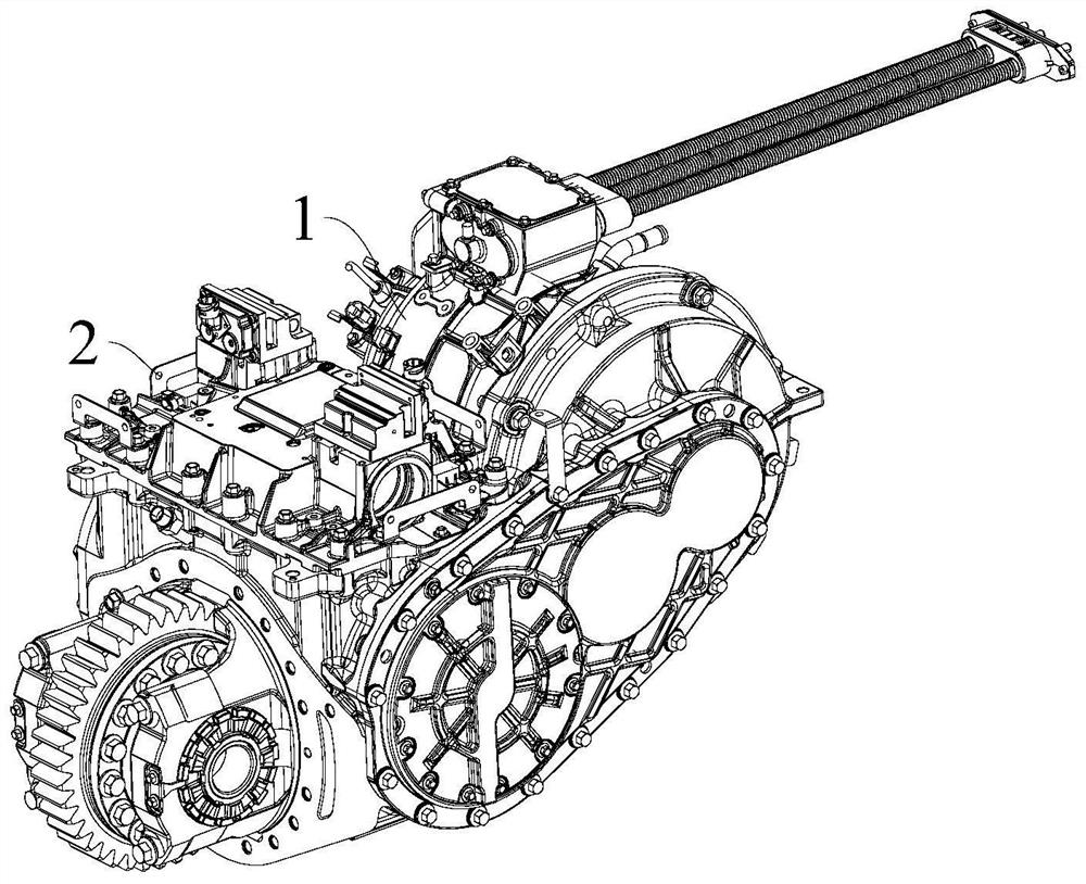
[0049] Reference below Figure 1-Figure 11 The transaxle assembly 10 of the vehicle of the embodiment of the present invention is described.

[0050] like Figure 1-Figure 11 As shown, the transaxle assembly 10 according to the embodiment of the present invention includes: a motor 1, a first gear 11, a second gear 12, a first shaft 13, a second shaft 14, a gearbox 2, a right shift fork 3, a right inner tooth Ring carrier 4, right sun gear 41, right inner planetary gear 42 and right ou...


PUM


Abstract

The invention discloses a drive axle assembly of a vehicle. The drive axle assembly comprises: a motor; a first gear, a second gear, a first shaft and a second shaft; a gearbox; a right shift fork; a right inner gear support; a right sun wheel, right inner planet and right outer planet; left shift fork, left shift fork movable between third and fourth positions; left inner ring gear holder; left sun gear and left planet gear, left sun gear with The right inner gear bracket rotates coaxially, and the left sun gear rotates synchronously with the second shaft; the driving gear, the driving gear rotates synchronously with the left planetary gear through the left planetary bracket; the differential, the differential is connected with the driving gear. Among them, the gearbox of the drive axle assembly of the present application adopts the coaxial arrangement of double planetary rows, which can increase the ground clearance of the vehicle, and when the gears in the drive axle assembly transmit torque, the gears have no idle gears, which reduces the oil churning of the gears. Power loss, improve the transmission efficiency of the transaxle assembly, and also reduce the operating noise of the vehicle.

Description

technical field [0001] The present invention relates to the field of vehicles, in particular to a drive axle assembly of a vehicle. Background technique [0002] In the related art, the structure of the drive axle assembly of the vehicle is complex, and the finished product is expensive; the assembly volume is large, and the drive axle assembly is assembled on the vehicle, resulting in a small ground clearance of the vehicle, and the weight of the drive axle assembly is heavier. During the driving process of the vehicle, a large torque will be generated on the joint surface of the axle assembly and the powertrain, and the joint surface will easily crack or the strain will be large, resulting in oil leakage. At the same time, the existing gear shifting method of the drive axle assembly is an electro-hydraulic module gear shifting, and the entire module has a complex structure, high price and high maintenance cost. When the drive axle assembly transmits torque, all the gears ...

Claims


Application Information

Patent Timeline
Patent Type & Authority Patents(China)
IPC IPC(8): B60K17/00
CPCB60B35/125B60K2001/001F16H2200/0021F16H3/666B60K17/02B60Y2200/91F16H2200/2007F16H2200/0043F16H2200/2041B60K17/08B60Y2200/14B60K17/20B60Y2400/4045B60Y2400/406B60Y2306/09F16H63/3023F16H2057/02034F16H2057/02052F16H61/30F16H61/0267F16H48/08F16H48/24B60K1/00B60K17/16F16H63/32
Inventor 方泽铭魏海龙全初鹏刘辉跃
Owner BYD CO LTD
Learn More