Mask alignment device and mask alignment method

A mask alignment and mask technology, which is applied to instruments, vacuum evaporation plating, coatings, etc., can solve the problems of low measurement accuracy, poor alignment accuracy between metal mask and frame, and improve alignment accuracy. , The effect of improving light utilization and improving measurement accuracy

Active Publication Date: 2022-02-18
SHANGHAI MICRO ELECTRONICS EQUIP (GRP) CO LTD
View PDF3 Cites 0 Cited by
  • Summary
  • Abstract
  • Description
  • Claims
  • Application Information

AI Technical Summary

Problems solved by technology

The metal mask is fixed in the frame by stretching and welding. During the stretching process, the position of the characteristic hole is measured by the measurement system. Due to the different types of characteristic holes, the measurement accuracy of the existing measurement system is low, resulting in the metal mask Alignment accuracy of mold and frame is poor

Method used


Image

  • Mask alignment device and mask alignment method
  • Mask alignment device and mask alignment method
  • Mask alignment device and mask alignment method

Examples


Embodiment

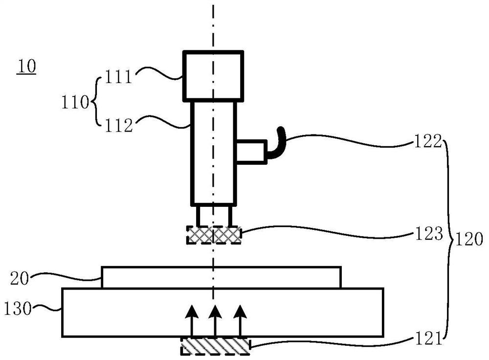
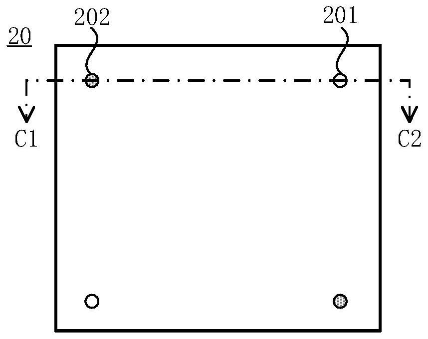
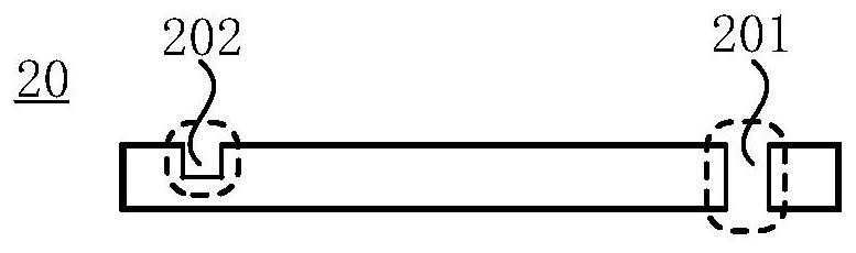
[0056] figure 1 is a schematic structural diagram of a mask alignment device provided by an embodiment of the present invention, figure 2 is a schematic diagram of the planar structure of the mask to be aligned that is aligned by the mask alignment device provided by the embodiment of the present invention, image 3 is along figure 2 Schematic diagram of the cross-sectional structure of C1-C2. refer to Figure 1-Figure 3 , the mask alignment device 10 includes: a detection unit 110, an illumination unit 120 and a workpiece stage unit 130; the illumination unit 120 includes a backlight light source 121, a coaxial light source 122 and a ring light source 123; One side of the unit 110; the side surface of the workpiece table unit 130 away from the backlight light source 121 is used to carry the mask 20 to be aligned; the optical axis of the coaxial light source 122, the optical axis of the ring light source 123 and the central axis of the detection unit 110 are all Coaxial ...


PUM

PropertyMeasurementUnit
widthaaaaaaaaaa

Abstract

The invention discloses a mask alignment device and a mask alignment method. The mask alignment device includes: a detection unit, an illumination unit and a workpiece stage unit; the illumination unit includes a backlight light source, a coaxial light source and a ring light source; the backlight light source is located on the side of the workpiece stage unit away from the detection unit; the workpiece stage unit is away from the backlight light source The one side surface of the light source is used to carry the mask to be aligned; the optical axis of the coaxial light source, the optical axis of the ring light source and the central axis of the detection unit are all coaxially arranged, and the coaxial light source, the ring light source and the detection unit are all located on the workpiece table The same side of the unit; the mask to be aligned includes positioning marks, and the positioning marks include through holes and / or grooves; backlight light source is used to provide illumination when positioning through holes, and coaxial light source and ring light source are used when positioning grooves Provide lighting. The technical scheme of the present invention can improve the measurement accuracy of the positioning marks in the mask, thereby improving the alignment accuracy of the mask and the frame.

Description

technical field [0001] Embodiments of the present invention relate to the technical field of mask plate measurement, and in particular, to a mask alignment device and a mask alignment method. Background technique [0002] Organic Light-Emitting Diode (OLED) has the advantages of self-illumination, no need for backlight, thin thickness, high contrast, fast response, wide viewing angle, and can be applied to flexible panels, etc., and its application prospects are very broad. The light-emitting structure of an organic light-emitting diode includes a cathode, an anode, and a light-emitting layer between the cathode and the anode. The light-emitting layer is usually manufactured by a vacuum mask evaporation process. [0003] During the vacuum mask evaporation process, a mask plate device is used for masking. The mask plate device generally includes a frame (frame) and a metal mask (mask). A large number of pixel holes and several feature holes are arranged on the metal mask. Ho...

Claims


Application Information

Patent Timeline
Patent Type & Authority Patents(China)
IPC IPC(8): G03F9/00
CPCC23C14/042C23C14/24H10K71/166H10K71/00
Inventor 陈雪影李运锋
Owner SHANGHAI MICRO ELECTRONICS EQUIP (GRP) CO LTD
Why Eureka
Try Eureka