
Sealing gas supply device for transonic turbine plane blade grid experiment

A gas supply device and transonic technology, which is applied in the field of sealed gas supply device for transonic turbine plane cascade experiments, can solve the problems of high requirements, restriction awareness, high experiment cost, etc., and achieve convenient processing and easy realization , the effect of simple structure

Active Publication Date: 2021-04-02
INST OF ENGINEERING THERMOPHYSICS - CHINESE ACAD OF SCI
View PDF6 Cites 2 Cited by
  • Summary
  • Abstract
  • Description
  • Claims
  • Application Information

AI Technical Summary

Problems solved by technology

Most of the existing turbine sealing experiments are carried out on the turbine-level component test bench or the low-speed large-scale rotating test bench. Although the full-stage experiment on the turbine can obtain the real influence characteristics of the seal flow on the mainstream, the full-stage experiment has no effect on The requirements for laboratory equipment and instruments are high, the cost of experiments is high, and it is difficult to achieve fine measurement of the flow field inside the turbine channel
In comparison, the planar cascade can conveniently, quickly and economically study some basic flow phenomena in the turbine, and has the characteristics of low cost, easy measurement, and convenient controllability. It has always been an important means for people to study the internal flow of turbomachinery, but The sealed outflow inside the real engine is a complex rotating flow with large axial, radial and circumferential velocities. However, due to the limitation that the planar cascade does not have rotating parts, it is difficult to reproduce the real flow in the planar cascade experiment. The jet conditions of the engine turbine seal flow, especially the circumferential velocity of the seal flow, are difficult to simulate, which severely restricts the understanding of the interaction mechanism between the real turbine seal flow and the mainstream

Method used


Image

  • Sealing gas supply device for transonic turbine plane blade grid experiment
  • Sealing gas supply device for transonic turbine plane blade grid experiment
  • Sealing gas supply device for transonic turbine plane blade grid experiment

Examples


Embodiment Construction

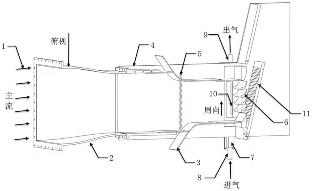
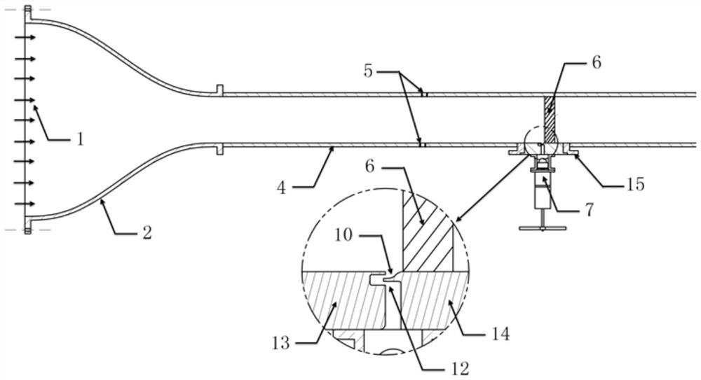
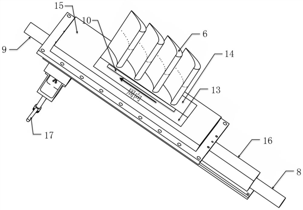
[0033]In order to make the objectives, technical solutions and advantages of the present invention clearer, the technical solutions in the embodiments of the present invention will be described in more detail below in conjunction with the drawings in the embodiments of the present invention. In the drawings, the same or similar reference numerals denote the same or similar elements or elements having the same or similar functions throughout. The described embodiments are some, but not all, embodiments of the invention. The embodiments described below by referring to the figures are exemplary and are intended to explain the present invention and should not be construed as limiting the present invention. Based on the embodiments of the present invention, all other embodiments obtained by persons of ordinary skill in the art without creative efforts fall within the protection scope of the present invention. The structure and technical solutions of the present invention will be f...


PUM


Abstract

The invention discloses a sealing gas supply device applied to a transonic turbine plane blade grid experiment. A transonic turbine blade grid is arranged on the end wall of a wind tunnel, a sealing gas supply cavity is formed in the outer side of the end wall of the wind tunnel, and a sealing gas outlet extending in the direction perpendicular to the main flow direction and located at the upstream position of the front edge of the transonic turbine blade grid is formed in the top of the sealing gas supply cavity. Sealing cold gas flowing out of the sealing gas outlet has the component velocity perpendicular to the main flow direction, is injected into a wind tunnel main flow passageway and interacts with main flow gas in the wind tunnel main flow passageway. By means of the characteristicthat the speed direction of cold gas in the sealing gas supply cavity is tangent to the circumferential direction of the transonic turbine blade grid, the circumferential speed of sealing flow can beshown again without rotation of components, and meanwhile the effect of independently changing the flow of the sealing flow and the circumferential speed of the sealing flow is achieved. The sealingjet flow condition required by the transonic turbine plane blade grid experiment can be fully simulated, the sealing flow characteristic in a real turbine is shown again, and a precise three-dimensional flow field structure is easy to obtain.

Description

technical field [0001] The invention belongs to the field of aero-engine / gas turbine transonic turbine plane cascade experiments, and relates to a sealed gas supply device used for transonic turbine plane cascade experiments. The present invention utilizes the characteristic that the velocity direction of the cold air in the air supply chamber of the seal is tangent to the circumferential direction of the transonic turbine cascade, so that the circumferential velocity of the seal flow can be reproduced without the rotation of parts, and at the same time, the seal flow can be changed independently The effect of the flow rate and the peripheral velocity of the sealing flow can fully simulate the sealing jet flow conditions required for the transonic turbine flat cascade experiment, which can greatly reduce the cost of the turbine sealing experiment. Background technique [0002] In modern advanced aero-engines, a large amount of cooling air and sealing air are required to ensu...

Claims


Application Information

Patent Timeline
Patent Type & Authority Applications(China)
IPC IPC(8): F01D11/04G01M9/04G01M15/02G01M15/14
CPCF01D11/04G01M15/02G01M15/14G01M9/04Y02E10/72
Inventor 屈骁张英杰张子卿张燕峰卢新根
Owner INST OF ENGINEERING THERMOPHYSICS - CHINESE ACAD OF SCI
Learn More