
A large depth of field infrared wavelength scanning lens

A wavelength scanning and infrared technology, applied in the field of infrared wavelength scanning lenses with a large depth of field, can solve the problems of narrow working distance range, inability to realize simultaneous scanning of near and far, limited size of photosensitive surface, etc., to achieve large working range and good energy Collection effect, satisfying the effect of small aperture

Active Publication Date: 2021-11-16
ZHEJIANG UNIV +1
View PDF13 Cites 0 Cited by
  • Summary
  • Abstract
  • Description
  • Claims
  • Application Information

AI Technical Summary

Problems solved by technology

In order to ensure the measurement accuracy, the size of the photosensitive surface of the detector is limited, generally in the range of several hundred microns in diameter. Therefore, in order to ensure the receiving energy, the working range of the general scanning instrument is limited to the near or far relative to the lens, and it is impossible to achieve near and far Simultaneous scanning at the same time, the working distance range is narrow

Method used


Image

  • A large depth of field infrared wavelength scanning lens
  • A large depth of field infrared wavelength scanning lens
  • A large depth of field infrared wavelength scanning lens

Examples


Embodiment Construction

[0062] In order to better illustrate the advantages and characteristics of the present invention, the present invention will be described in detail below in conjunction with the accompanying drawings. The described embodiment is only one embodiment of the present invention, and all other embodiments obtained by persons of ordinary skill in the art without making creative efforts fall within the protection scope of the present invention.

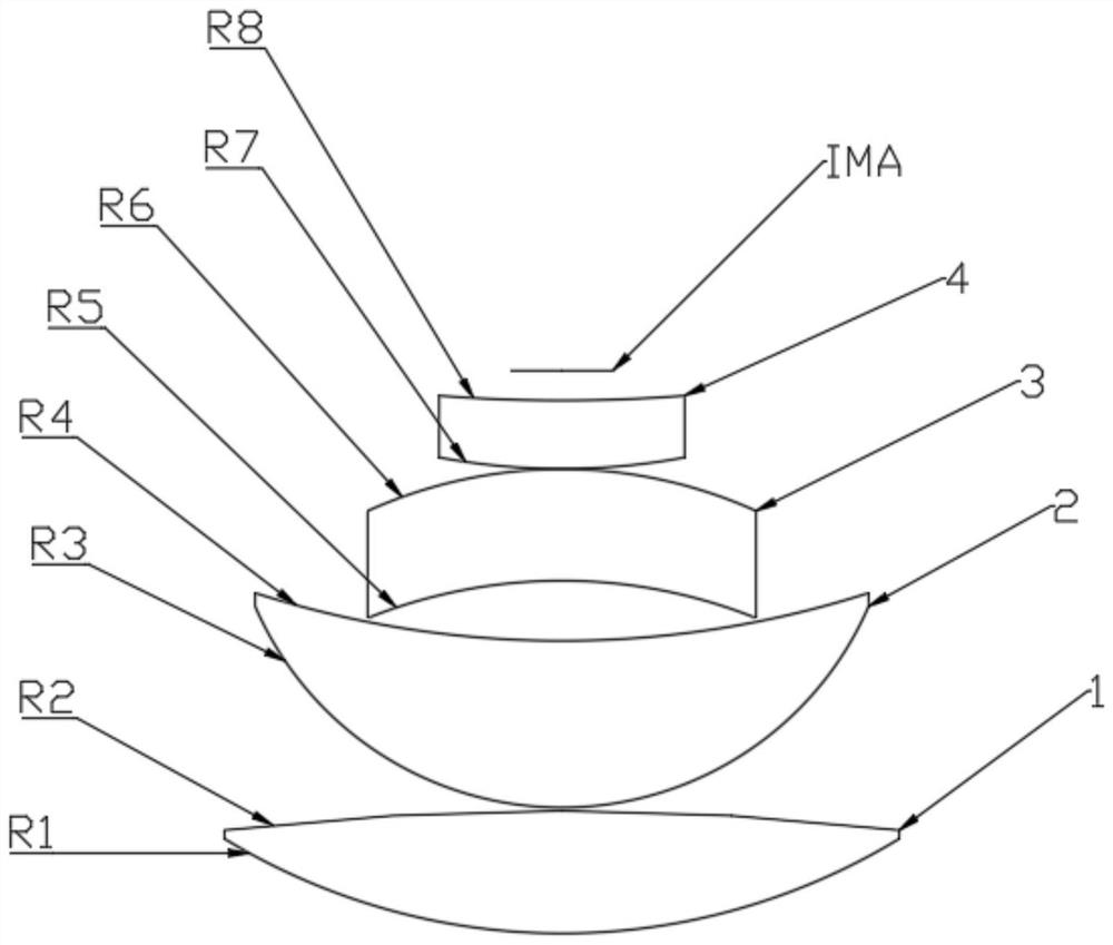
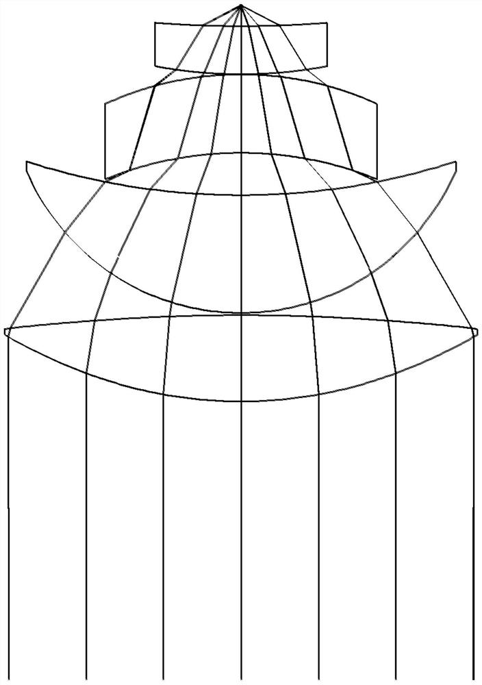
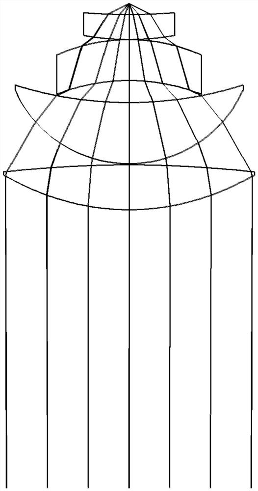
[0063] Referring to the accompanying drawings, the present invention provides an infrared wavelength scanning lens with a large depth of field. figure 1 Shown is a large depth-of-field infrared wavelength scanning lens according to the first embodiment of the present invention, and the scanning lens includes four lenses. Specifically, the large depth-of-field infrared wavelength scanning lens is sequentially arranged along the optical axis from the object side to the image side: a first lens 1 , a second lens 2 , a third lens 3 and a fourth l...


PUM


Abstract

The present invention proposes a large depth-of-field infrared wavelength scanning lens, comprising a first lens, a second lens, a third lens and a fourth lens, and the first lens, the second lens, the third lens and the fourth lens extend from the object side to the image The direction of the square is set sequentially on the optical axis, and finally the light energy is converged on the image plane. The first lens is a biconvex positive lens with an even aspheric surface, and the second lens, the third lens and the fourth lens are all concave-convex. Spherical positive lens. The typical wavelength of the system is 1550nm, the total focal length F of the system and the entrance pupil diameter d satisfy: 2

Description

technical field [0001] The invention relates to the field of designing optical lenses, and in particular relates to a large depth-of-field infrared wavelength scanning lens suitable for optical measuring instruments such as scanners and total stations. Background technique [0002] With the improvement and scale expansion of construction industry and manufacturing technology, as well as the increasing demand of contemporary people for the protection of architectural cultural heritage, the demand for 3D modeling of architectural and processing structural parts is increasing day by day. Three-dimensional scanning technology is divided into contact and non-contact. For architectural modeling, component processing and other fields, only non-contact three-dimensional scanning can be used. It uses laser to load modulation signals, and after emission, it is reflected back to the receiver through the scenery. The system is collected on the photosensitive surface, and the distance in...

Claims


Application Information

Patent Timeline
Patent Type & Authority Patents(China)
IPC IPC(8): G02B13/18G02B13/14
CPCG02B13/004G02B13/008
Inventor 黄腾超孙澍宇杨建华车双良周一览舒晓武陈刚陈依铭
Owner ZHEJIANG UNIV
Learn More